6 Valve VHF/FM Pulse Counting Tuner Using Safe 25 Volt DC HT Line
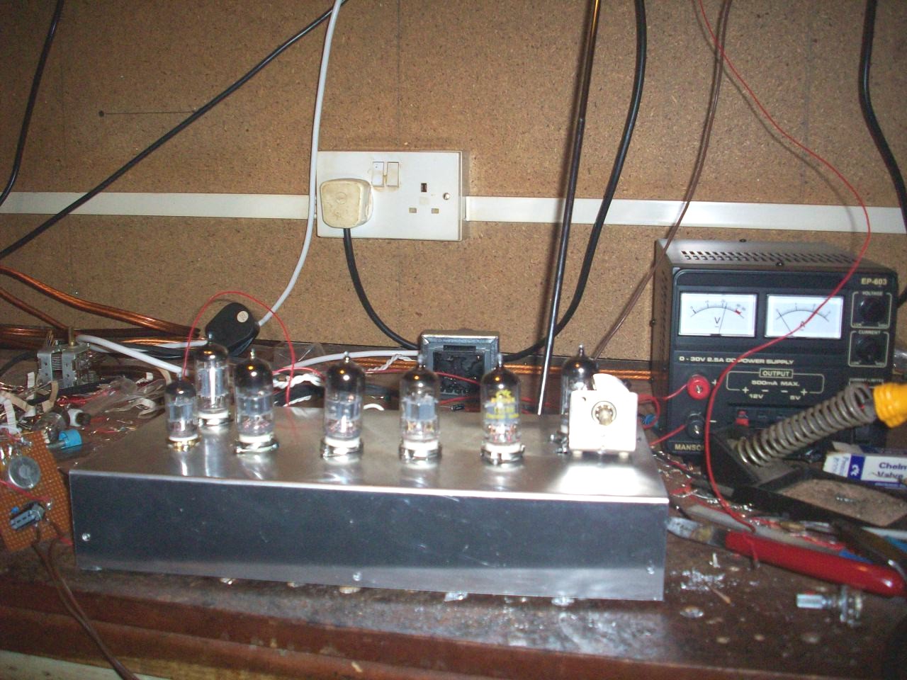
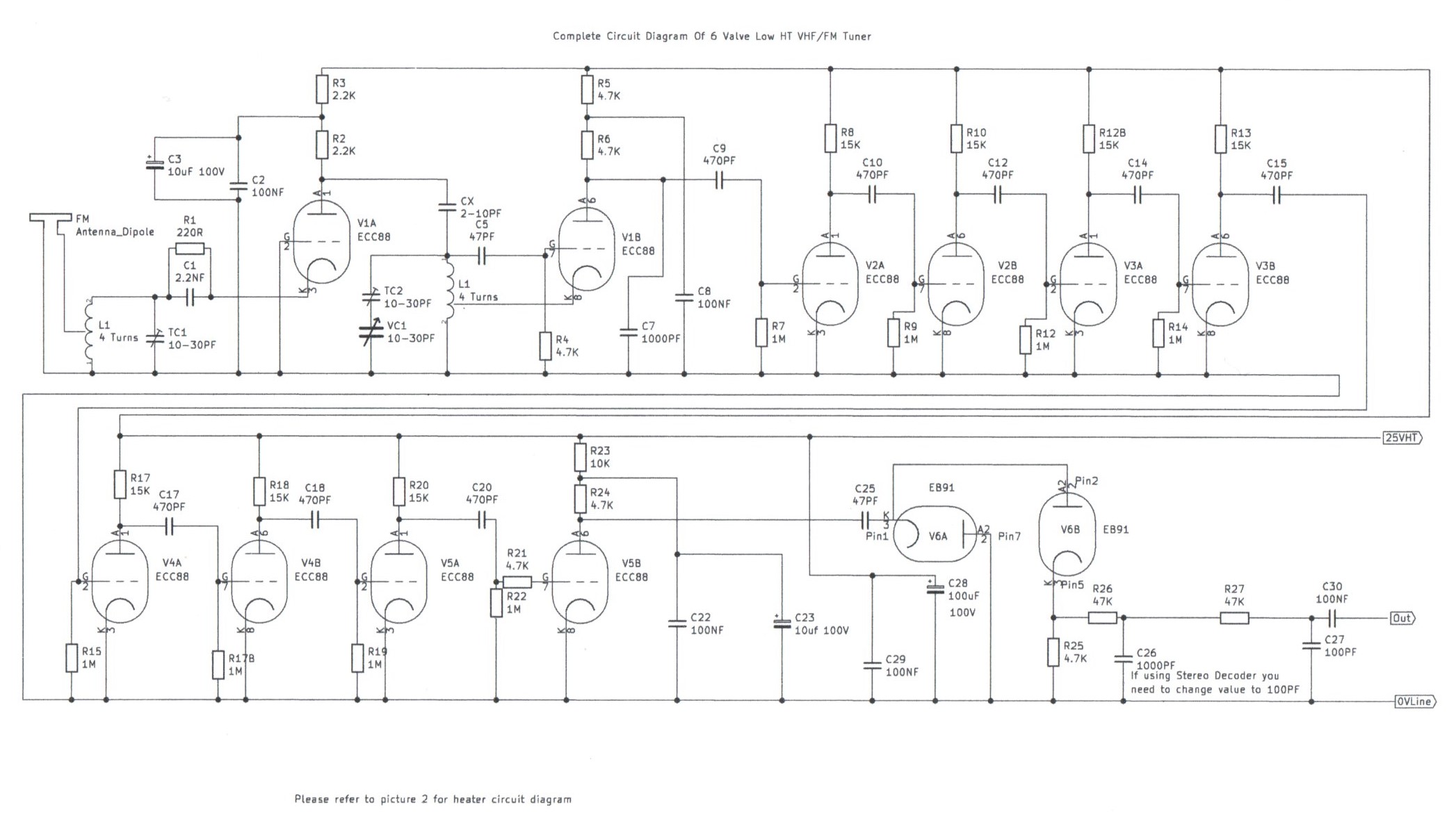
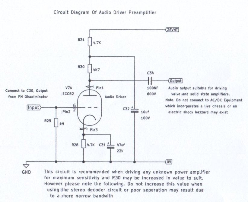
This part of my site features a valve version of the VHF/FM Pulse Counting FM Superhet Receiver. It works very much in the same way as my Transistor Pulse Counting FM Receiver but uses valves and the unusual thing about this design it will work on low voltages even as low as 15 volt if the local oscillator anode decoupling resistor is optimized to a lower value to suit. Low voltage operation of valve radio circuits is not really anything new and circuits for 1or 2 valve regenerative short wave receivers have appeared in radio magazines of that era. Also car radios of the late 50s used this method using special space charge valves designed for 12 Volt operation for the radio section and the usual AD161 and AD162 germanium power transistors used for the power output stage to drive a loudspeaker. It was still necessary in some cases to use valves particularly if it was a portable FM set as transistors suitable for VHF work had not quite caught up in technology until the early 1960s. Although RF and IF amplification is possible using normal mains valves at these low voltages, the power output is very limited because the emission of the cathode current is only about 1 to 3 milliamps at these voltages. However. If you are in a quite listening environment such as a bedroom or small office you can get usable results of about not more then 3 miliwatts of audio power from a small EL84 power valve or an even more economical valve such as the ECC86 designed for low voltage operation. The ECC86 has a cathode current of 10 milliamps per triode and will give a loudspeaker output of about 100 milliwatts from the main 25 Volt HT line at very pleasing volume and good audio reproduction. It also takes less heater current then the other power valves. The pulse counting superhet receiver became a popular circuit for amateur Hi Fi experimenters during the mid 1960s to early seventies as a low cost means of receiving FM in Hi Fi quality Mono and the advantages of it is there are no 10.7 MHZ IF transformers involved or hours of RF alignment of Ratio Detectors to get a design that is distortion free working almost first time when powered up. The disadvantages of the pulse counting receiver is the low IF bandwidth available for reliable multiplex stereo transmissions for feeding a stereo decoder along with the 19KHZ pilot tone and 38KHZ subcarrier. Although it is possible with this design the separation is not as good compared to the 10.7 MHz Ratio detector and needs a far more stronger signal then mono of around 60db for hiss free reception. I will describe how mine valve version of the pulse counting FM receiver works as follows. This design uses 5 double triode ECC88 valves for the RF Amplifier, Mixer and IF Amplifier and although they have become a popular audio valve for preamplifier applications it was originally designed as a framed grid VHF Valve for use as a cascode VHF RF amplifier and self oscillating mixer in Television and FM Receivers. I had a good collection of ECC88s and found out by experimenting with a 1 valve VHF Regenerative Receiver that they work very well with low anode voltages of around 7 volts. Referring to the block diagram and circuit diagram of picture 5, V1A functions as a wide band grounded grid RF amplifier and although it does not really provide very high gain its purpose is to isolate the VHF Antenna from V2B that would otherwise course detuning effects resulting in unreliable oscillation when tuning certain frequencies of the FM band and most importantly of all, oscillator radiation that can effect the reception of nearby receivers. V2B is an electron coupled self oscillating Autodyne mixer and although its appearance is very similar as the regenerative detector used in the Simple 2 Valve Regenerative Receiver it can perform both functions as an oscillator and frequency converter with 1 RF tuning coil. The reason for 1 coil performing both tasks is because the 250KHZ IF frequency separation is so small that there is hardly no loss in RF gain and with a normal 15PF tuning capacitor it is possible to tune the entire FM band between 87.5 MHZ to 108 MHZ. This section alone can also function as a 1 valve regenerative receiver which was an experiment that led to this design. The 1000PF decoupling capacitor C7, function along with the C15 grid coupling capacitor for V2A to form an IF filter to reject the VHF megacycle frequencies and only amplify the wanted low frequency of 250KHZ through the IF stages. V2A to V5A function as a 7 stage 250KHZ Intermittent Frequency Amplifier. The 470PF grid coupling capacitors C9 C10 C14 C15 C18 and C20 set the IF frequency response to around 250KHZ. V5B functions as a limiter by applying a slightly lower plate bias to this stage and the clipped wave form is then applied to the demodulator stage. The V6 6AL5(EB91)Valve functions as a voltage doubler diode pump charge FM Demodulator and the resistance capacitive filter R25 R26 R27 along with C26 C27 and C30 form a simple deemphasises filter to reduce background hiss and also sets the frequency response of the transmitted audio to the UK time constant of 50 microseconds before being amplified to an audio signal. Although this tuner was originally planned as a 6 valve design the V7A ECC82 half triode section functions as a AF voltage preamplifier to amplify the audio signal to a suitable level to drive any valve or transistor amplifier. V7B is not needed unless you decide to add a power amplifier stage into this tuner and to avoid cathode poisoning its heater must not be connected unless the reason to use this section is required. This tuner if built properly performs just as well and in some cases better then FM tuners that need a higher voltage HT line. It has also been designed with safety in mind using a low 25 volt HT line and providing care in the construction of the recommended power supply unit in picture 3 is taken, this receiver should provide many happy hours of pleasure. Please click on the following link YouTube - Phil's design of a valve FM pulse counting tuner using safe 25 volt HT line to hear this design working and refer to the guidelines and diagrams below for construction details. Important notice, Please read further. If you have read on the home page all hand drawing is being removed from this entire website and this is going to be one of the first pages to have the revamp. The circuit diagram in picture 3 has already been done. Please note that this work will happen gradually as time permits
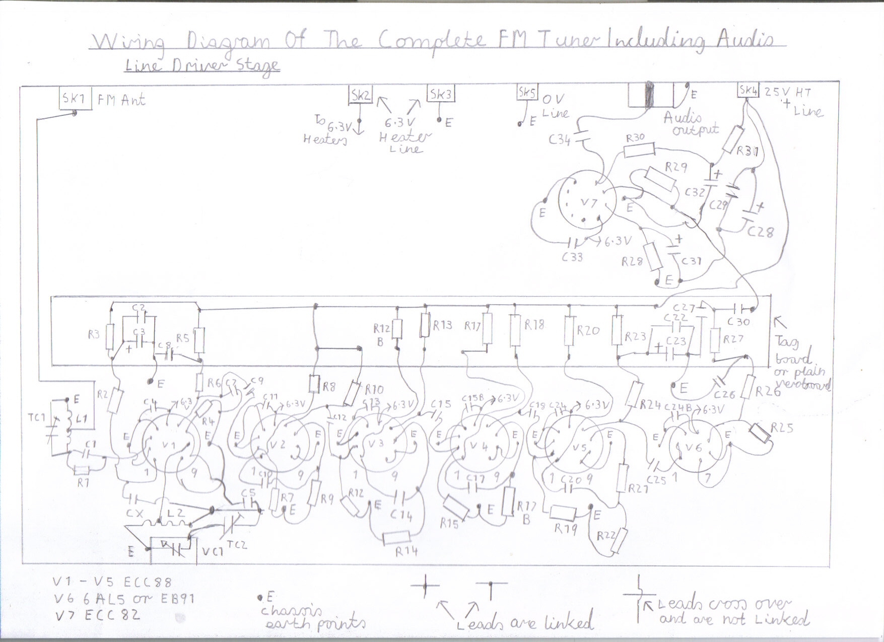
Circuit Diagram Of The 6 Valve Pulse Counting FM Tuner
|
|
|
|
|
|
|
|
|
|
|
|
|||
Construction Details Of This FM Tuner
Step 1. Important points to know regarding safety and general construction tips
Although this is the safest valve project to build on this site using a safe 25 volt HT line there are several safety precautions that need to be born in mind as you are still dealing with 240 volts AC mains.
1. You must only use the recommended power supply circuit as described in pictures 3 and 4 and all mains connections must be covered using proper insulated materials and an earthed metal case is essential with a screw fitted lid so no dangerous live parts are accessible.
2. You must use the correct rating of fuses for the power supply circuit. The FS1 1 Amp mains fuse only protects the mains side of the power supply in the case of a faulty switch, wiring or a fault in the primary of the mains transformers. The FS2 100ma HT fuse in series with the bridge rectifier protects all the low voltage circuitry and T2 Secondary from overloads. This fuse will blow immediately if there is any serious fault such as a short circuit or high current overload on the HT output. Do not for any reason increase this fuse higher or try the old tricks such as tinfoil or cigarette paper to stop this fuse from repeatedly blowing or you may burn out your mains transformers and there could be a big risk of fire.
3. You must also take care regarding the polarity of the electrolytic capacitors. Always make sure that the positive plus + side corresponds as shown in the circuit or wiring diagram and it is recommended that these capacitors are rated at no less then 35 volts for this circuit. Incorrect polarity of the electrolytic capacitors can result in them exploding and can also be dangerous.
4. The valve heater wiring regarding the current rating along with the heater transformer must be taken into serious consideration as the heaters are the most current hungry of the entire tuner. The 6.3V valve heater circuit with all 7 valves in circuit consumes 2.35 Amps. Although a mains transformer that provides 6 volts at 2.5 Amp would be the nearest safe option I would recommend around 3.5 to 4 Amps in case you might decide to upgrade it with a power amplifier using the popular EL84 or ECL82 output valves. Also you must use the proper 6 Amp stranded or bell wire twisted to cancel mains hum from the outgoing connection from the power supply to the tuner. The aluminium chassis acts as an earth return for all the heaters in circuit so you must also make sure all solder tags and bolts are securely tight or sparking and crackling noises will result, spoiling the good performance of this tuner. The 100N ceramic disk capacitors that are parallel connected across the heaters of V1 to V7 that is C4 C11 C13 C16 C21 C24 C33 are RF bypass capacitors to help prevent feedback of VHF oscillations flowing though the heater circuit and must not be omitted.
5. It is important that this tuner is built in a diacast or aluminium chassis to prevent radiation of the local oscillator from effecting the reception of nearby FM receivers tuned to the same reception frequency. It is also advisable to make sure you have a bottom lid on the chassis to screen the VHF circuitry. The use of a wooden chassis to make the receiver look like the 20s and 30s style of design is not recommended for the same reason I have just mentioned. Also VHF designs, weather regenerative or of the superhet design do need a decent ground plain to work really well regarding stability.
5. Important points to remember about connecting to other audio amplifiers. The ECC82 Line driver stage will feed any IC audio amplifier of the LM386 and TDA7052 variety without any problems and should be able to drive almost any transistor amplifier. Connecting to other valve amplifiers should also pose no problem providing the following points are born in mind. First of all you must make sure the anode coupling capacitor C34 of the audio driver stage is rated at least about 400-1000 volts as a high voltage fault on the input in which you are connecting to may damage components and could pose an electric shock hazard. Some of the older valve amplifiers such as the Quad and Mullard 5-10 variety that were around in the 50s have HT and LT sockets for powering ancillary equipment such as preamplifiers and tuners. Again this voltage is far to high for feeding this tuner and because the heaters may be centre tapped at 3.0.3 volt to earth, this sort of supply would be very unsuitable. Finally on a closing point regarding safety there is one kind of valve amplifier or radio that this tuner must on no account be ever connected to unless a suitable earthed mains isolation transformer is used. It is of the AC/DC variety that uses a live chassis and does not incorporate a mains transformer. A big green dropper resistor usually exists along with the UCL82 and UY85 type valves with there 100ma heaters. The Mullard 4-7 push pull amplifier falls into this category and could pose a very lethal electric shock hazard. However, with a suitable earthed isolation transformer these problems can be safely overcome.
Step 2. Component Availability
There is one good advantage when building valve equipment that uses a low voltage HT line. The smoothing electrolytic capacitors that are used in the power supply and receiver itself are more easier to obtain along with other components because of there lower voltage rating required. Resistors apart from in some rare cases, need only be 1/4 of a watt because of the low power and heat consumption involved. The only really hard items to obtain for this design are the tuning capacitors, through not impossible there could be a lengthy wait depending on the response of the delivery concerning the order of these hard to get components, due to excessive demand. It is also possible to use old 365PF tuning capacitors found in medium and short wave receivers if a series 10-30PF trimmer is used to reduce the capacitance, although there is a high risk of electrical backlash involved such as scratchy tuning particularly if the vanes are shorting together or have been damaged due to corrosion. Please click on the following link Components List Of 6 Valve VHF/FM Tuner for full information regarding the components for this tuner and lists of suppliers
Step 3. Wiring And Testing The Power Supply
This is where the greatest of care must be taken as this involves 240 Volts AC Mains and any slight error regarding the wiring of the mains connections, particularly the earthing could lead to a serious risk of electric shock. If you are unsure about how to proceed with the wiring and testing of this unit then at least get an electrician to check the mains wiring before plugging it in and switching on.
1. If you have got all components to hand then please refer to picture 3 for the circuit diagram and picture 4 for the wiring diagram.
2. You need a multimeter capable of being able to read at least 500 Volts AC and 500V DC
3. It is best to get all components such as the mains transformers, switches and fuse holders mounted into the case first before wiring everything up and mounting the circuit board.
4. Start by doing the mains wiring first, making sure all solder joints are neat and tidy with no dry joints.
5. Make sure the green and yellow core of the mains cable is securely tight on both earthing points of the mains transformers as shown in the wiring diagram.
6. If you are sure all mains wiring is correct you can actually test this side of things without plugging the unit in. It is called a continuity test which is also carried out on all house electrical installations before connecting and switching on.
7. Inset the mains lead including FS1 but do not on any account attempt to plug in and switch on
8. Set your multimeter to the 500 to 1000 Ohms range.
9. By touching your test probes on the live and neutral pins of the plug you should get a reading of around 50 to 500 Ohms depending on the resistance of the mains transformers. If this reading is zero Ohms which means a full reading when using an analogue meter then something is seriously amiss such as a short circuit somewhere in the wiring and must be investigated.
10. Try rocking SW1, the mains switch on and off to check this also works correctly.
11. If all the above tests are OK it is now time to carry out an earth continuity test.
12. Touch the metal case of the unit with one of your test probes and at the same time touch the earth pin of the plug with the other probe. There should be a zero Ohms reading which means a full reading when using an analogue meter. If this is so proceed to the next instruction.
13. Repeat the above procedure touching the neutral pin and earth pin at the same time with your test probes and repeat this test by touching the live and earth pin with your probes. If you do not get any reading whatsoever at this stage then the above tests have gone OK and this power supply unit will be absolutely safe to use when completed.
14. If all the above procedures have gone OK it is now time to wire up the circuit board.
15. Please refer to the wiring and circuit diagrams in pictures 3 and 4 taking care that you observe the polarity of components such as the bridge rectifier and the C1 electrolytic capacitor. The flat side of the regulator must mount flush with the circuit board and a heat sink is not required because the current demand of this tuner is so low that it hardly gets warm.
16. The circuit board can now be mounted into the case as shown in picture 3 and the output side of the power supply can now be wired up.
17. Make sure you use the white 6 Amp cable for wiring the 6.3 Volt output and you must lightly twist these leads to cancel mains hum.
18. Make sure that the 0V negative side of the 25V HT output is connected to the mains earth at the solder tag bolt of T1.
19. If you are confident you have gone through all the above procedures correctly it is now time to test this unit where the greatest of care must be taken.
20. Set your meter to the DC volts range of around 50V and using crocodile clips on each probe connect the red and black probes to the 25 volt DC output observing the correct polarity.
21. Try to use a mains socket that is at least a metre clear of the unit when first switching on in case of the event of C1 exploding due to incorrect polarity. Also be very careful not to touch any mains circuitry within the unit as it will be live.
22. Switch on and stand clear for a short moment and if all is well you should get a DC reading on your meter.
23. If it is only say 10 Volts, rotate RV1 clockwise until you get the correct reading of 25 Volts DC.
24. If all the above tests seem ok, switch off the unit and set your meter to the AC volts range of about 20V
25. Repeat the above procedure but this time connect your probes to the 6V AC Output in ether polarity.
26. You should now get a reading of around 6.3 Volts off load.
27. If all these tests and procedures have gone OK, the construction of the power supply is now complete and you can now go ahead with constructing the FM Tuner.
Step 4. Preparing the Chassis
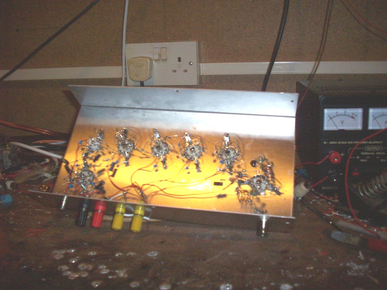
Preparing the chassis of a valve receiver and wiring the valve heaters is the most time consuming of constructing the entire receiver and if rushed and not done properly it can result in poor performance and instability. It is best to have all the components to hand that are physically mounted on the chassis before proceeding so you can familiarize yourself with them and determine the hole sizes for each component before carrying out the drilling. Before mounting any component make sure every hole required for drilling has been carried out so all the components can be mounted in one go. You must also make sure the chassis is clear of any debris such as metal filings before even attempting to install any component or short circuits may occur. Please read the following steps and guidelines before proceeding.
1.Please refer to picture 7 which is the wiring diagram. This diagram is also the best recommended layout of this tuner.
2. Start drilling all the required holes for V1 to 7 including the holes for the 2 6BA bolts of each holder. A 22.5 millimetre cutting tool is required for all the B9A nine pin holders. The V6 B7A holder requires a 16 millimetre cutting tool. Unfortunately these tools are not easily available as they once were and you may have to resort to filing out the correct size hole. Allow at least 25mm space 1 inch between each holder when mounting.
3. The front panel hole for the tuning capacitor can now be drilled along with the other holes for all the back panel sockets.
4. If you are confident all the drilling is now completed you can now go ahead with mounting all the required components
5. Chassis points marked with an E are essential earthing points which connections are usually made by a solder tag bolted to the chassis. You must make sure all these connections are clean with no grease and are physically screwed tight to the chassis or sparking may occur. Also it is advisable to have at least 3 solder tags on each bolt in which the valve holders are mounted to so neat and sound solder joints can be carried out without say 6 or more leads crammed onto 1 joint that can lead to dry solder joints, an avenue for poor performance.
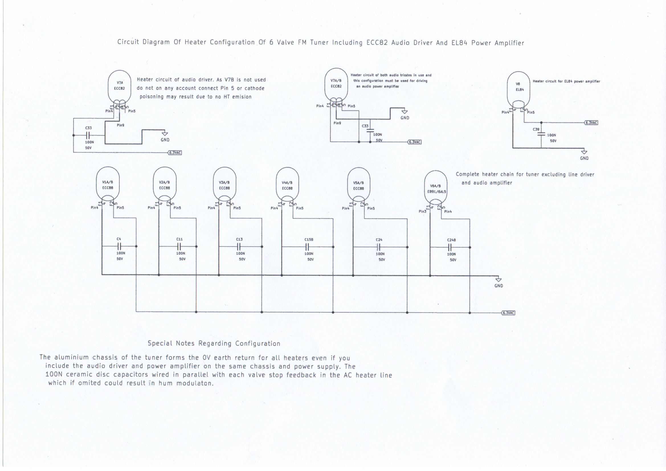
Step 5. Wiring Up The Valve Heaters
1. Please refer to picture 8 which is an individual wiring diagram of the valve heater connections.
2. As you can see, this may seem an unusual method of connecting the 6.3 volt AC heaters as there leads are usually twisted to cancel mains hum and this idea came from a VHF design featured in a 1960s Practical Wireless magazine using this same exact method that led me to give it a try and as it turned out to be it seems to work very well with no traces of mains hum. The other advantage is it makes the wiring less crammed and the 0.1uf ceramic disc capacitors connected across each heater help to suppress modulation mains hum as well as there role in helping to prevent VHF oscillations from circulating through the heater line.
3. Start by following the wiring diagram very carefully and try to avoid dry solder joints on the solder tags. Double check that all solder tags are very tight and that there is no sign of any movement. 1.5 Amp tinned copper wire can be used for interconnections to SK2 but you must make sure the 6 Amp size wire is used on connections between SK3 and the Chassis ground.
4. There is 1 important point concerning the heater wiring of the audio preamplifier valve ECC82 V7. It is centre tapped at pin 9 and wired for 6.3 Volt operation rather then 12.6 Volts so you must always make sure pin 9 is at earth potential. Pins 4 and 5 are usually parallel wired but because the V7A half triode is only needed at the moment you must only connect to pin 4 or the cathode coating will become poisoned due to no electron emission. V7B can serve as a driver for an additional power amplifier using an EL84 Valve which will be featured as an add on item.
5. If you are confident everything has been wired correctly regarding this stage you may give it a test.
6. Connect the SK2 and SK3 heater terminals of the tuner chassis to the SK1 and SK2 6.3 Volt output of the power supply using lightly twisted 6 Amp wire.
7. Insert all the valves of V1 to V7 in there referring holders.
8. Switch on the power and within 1 minute all the valve heaters should start to glow red.
9. If this is the case, everything has gone well so far and you can now proceed to the initial wiring of the tuner.
9. Switch off the power and allow the valves to cool for around 15 minuets.
10. Remove all the valves and put them back into there protected cartons until they are next needed.
11. Please refer to step 6.
Step 6. Wiring Up The Main Tuner
If you have followed all the above procedures correctly you can now go ahead with wiring the main FM Tuner. If you are familiar with the testing and setting up my Transistor Pulse Counting FM Receiver design, unfortunately you can't with this valve design test each stage as you build like you could with that design. The reason being it means reinserting the valves several times which may weaken the glass structure around the pins due to stress and the electrolytic capacitors may hold a charge in which you may encounter not so much of a shock at this low voltage but a few sparks if you accidentally short these components to ground.
1. Please refer to pictures 5, 6 and 7 for the complete circuit and wiring diagram of this receiver and the Components List Of 6 Valve VHF/FM Tuner
2. There are 2 slight errors regarding duplicate numbering of the following components on the original circuit diagram of picture 5 that were corrected in the wiring diagram of picture 7 and Components List Of 6 Valve VHF/FM Tuner which I will explain. The anode load resistors of V3A and V4A was incorrectly marked as R12 and R17 in the original circuit diagram of picture 5. These have been recorrected as R12B and R17B.
3. If you are confident you understand the circuit and wiring diagram you can now go ahead with the basic wiring.
4. Try to keep all wiring neat and short as possible, particularly in the VHF circuits of V1A and V1B and do not have unnecessary long leads connecting between the tuning capacitors and RF coils or this may lead to poor performance and loss of frequency coverage at the high 108MHz portion of the FM Band. Make sure you pay attention to the polarity of the electrolytic capacitors for the same reasons I mentioned in the construction of the power supply circuit. Also try to avoid dry solder joints and if possible try to leave the heat sensitive components until last such as the small 1/4 watt resistors.
5. Tinned copper wire is best for all the interwiring of all these stages and it pays to check your wiring now and again in each stage for short circuits such as solder bridges or leads crammed close together that are a very likely cause. The points marked E as I previously mentioned are chassis earth points and also form the 0V earth return for this tuner and you must double make sure these bolts that hold the solder tags are very tight to avoid backlash or other instabilities such as sparking.
6. The RF Coils L1 and L2 are self supporting and 18 SWG tinned copper wire must be used for there construction. If this wire is hard to obtain then 1.5 Amp lighting cable with its conductors striped will do the job just as well. I have decided that the enamelled copper wire used in the Transistor Pulse Counting FM Receiver is not suitable particularly for L2. L1 requires about 5 turns with a diameter of 9mm and a tool such as a AAA size penlight battery will surface. L2 requires the same number of turns but is tapped at 1 to 2 turns to form the cathode tap and normal tinned copper wire must be soldered to this tap to avoid stress on the valve holder pins of V1B
7. If you are now confident that you have wired everything correctly you may now refer to step 7 the initial testing and setting up of this FM tuner.
Step7. Testing And Setting Up
This is where the big moment of truth begins. Fortunately there is not the usual high voltage electric shock fears associated with this tuner, like there is with circuits that involve the usual 250 volt HT line. Valves are very electrically robust compared to solid state circuits and the only costly mistake due to connecting this tuner with wrong polarity to the 25 Volt HT line is damage to the electrolytic capacitors. The other common mistake is getting the pin 6 anode pin of each triode confused with the pin 5 heater connections which will immediately burn out the heater of the valve concerned but this is less likely if you have gone through the correct procedure of step 5.
1. Reconnect the valve heater circuit in the same procedure as previously described in step 5.
2. Using the normal black insulated tinned copper wire, connect the SK3 Black 0V terminal of the power supply to the SK5 Black 0V terminal on the back panel of the tuner
3. Using the normal Red insulated tinned copper wire, connect the SK4 25 Volt HT terminal to the SK4 25 Volt HT terminal on the back panel of the tuner.
4. As a final reminder double check all wiring and the polarity of all the electrolytic capacitors making sure the positive + corresponds as shown in the circuit and wiring diagram.
5. Insert all the 7 Valves.
6. Connect the audio output to any suitable amplifier and make sure it is turned on and the volume advanced around halfway.
7. Connect a suitable FM antenna to the SK1 coaxial input preferably an outdoor or indoor Dipole of about 1.5 metre will do for the time being.
8. Reconnect the power taking the same precaution as described in the construction of the power supply in step 3.
9. Within a minute as the valves get warm you should hear some static hiss which means there are good signs of life.
10. Try rotating the tuning control VC1 and it may be possible to receive a few FM stations.
11. If this is so try adjusting the TC1 aerial trimmer for maximum signal strength.
12. If all the above procedures have gone to plan it is now time to set and align the frequency coverage
13. If you are familiar with tuning the UK FM band, depending on your state of origin and know how the stations are located on the dial then the setting up can be done without the aid of a signal generator.
14. In the instance of the UK FM Band, try to locate BBC Radio 2 which is at the bottom end of the band around 87.5 to 90.2 MHZ.
15. If you find you are tuning Radio 2 with the VC1 vanes over halfway open then this needs correcting which I will describe.
16. TC2 in series with the VC1 tuning capacitor sets the frequency coverage. When the vanes of TC2 are fully open it lowers the capacitance of VC1 and sets the frequency coverage in the high frequency direction. The opposite is true if you have the vanes of TC2 fully closed. You are then setting the frequency coverage of VC1 in the lower frequency direction because you are effectively making the capacitance of VC1 higher.
17. To correct the case of you receiving Radio 2 with the VC1 tuning capacitor vanes half way open we need to gradually open the vanes of TC2 and keep retuning radio 2 until you can receive it with VC1 vanes open around a quarter of the way. You may find when fitting the bottom aluminium panel that this may also alter the frequency coverage slightly and may need a bit of experimentation to correct. This is due to magnetic effects.
18. If the above alignment has gone OK, try tuning a weaker local station further up the band say around 95 MHZ which is just past BBC Radio 4, the middle of the FM band.
19. Readjust TC1 the aerial trimmer for maximum signal strength. This should now correctly set the tuning range and by tuning further up the band you should be able to tune in stations such as Classic FM at equal strength with no background hiss or distortion.
20. If you are finding the V1B mixer and oscillator come to a holt when you are most likely to be tuning around the lower part of the FM Band you need to do the following procedure.
21. Increase the Cathode tap from 1 turn of the earthy side of L2 to around 2 turns. If this does not improve things much, try reducing the CX aerial coupling capacitor to a lower value of around 5PF or replace with a 2-10PF Trimmer. Also having the power supply set below 20 Volts can also be a likely cause so it may be as well check this before carrying out these procedures.
22. If everything has gone well to plan you should now have a complete working valve FM tuner of all your own work and I wish you all many happy hours of listening enjoyment. Remember nothing beats the cosy warm glow of a valve on cold winter evenings that solid state does nowhere archive
22. An optional power amplifier circuit with its own HT power supply circuit is described in pictures 9 and 10. It is capable of giving a decent loudspeaker volume of about 200 Miliwatts. Please refer to step 8 for further details if you wish to include this item.
Step 8. Adding The optional Power Amplifier
An optional power amplifier using an EL84 Output valve has been included for those who want to use the FM tuner as a portable anywhere in the home type receiver and although not HI FI quality it is capable of giving a output power of about 200mw about the same volume of the old battery valve receivers that use a DL96 pentode. Unfortunately there is not enough cathode emission when using a 25 Volt HT line to get good results regarding decent volume when using a speaker. A separate 67 Volt power supply is needed and is described in picture 10. It must also be built in the same case as the existing 25 Volt power supply or can be mounted on the receiver chassis provided it is big enough to allow room. The 67 volt HT line needs a bit more precaution then the 25 Volt HT line you are using to power the tuner and preamp section. Although the 67 Volt HT line is still nowhere as dangerous as the normal 250 Volt HT line you can get some nasty jolts if accidently touched so do take care with this stage of the construction. You also need to refer to picture 9 which is the circuit and wiring diagram combined together. The other half triode of V7B is also used for the driver section which means pin 5 of the valve base must be strapped to pin 4 to enable the heater of the V7B triode section. To save money on buying expensive output and HT transformers for this circuit the following link Maplin Electronics have the 2 transformers in question and work very well with this amplifier circuit. The output transformer is a 100 Volt line 2 watt PA transformer Code N85CC at the time of writing. The mains transformer is a 24.0.24 Volt 6VA miniature transformer Code N98CC and will power this amplifier very comfortably with no overheating effects. Also 240 Volt to 12 Volt mains transformers may also work with this circuit if the recommended output transformer is for some reason hard to obtain. There is a useful link 6BM8 Valve Audio Amplifier which has some detailed information on using line and mains transformers for valve output transformers and talking of the 6BM8 Valve audio amplifier, it is the Mullard ECL82 version and will also work very well if not better at 67 Volts HT then this EL84 version. Please refer to the Components List Of 6 Valve VHF/FM Tuner for the other components. Also if you would like to see a short video clip of this EL84 configuration, now working in a chipboard case please click on the following link YouTube - Revival Of My 6 Valve VHF Receiver In A Chipboard Case With EL84 Output Stage.MP4 which should put you in the picture of how it sounds. I have indeed got some good news for those wanting to have the receiver and power amplifier working at an all low voltage 25V HT Line. I have compiled a new power amplifier circuit in picture 11 based on the ECC86 triode valve and it gives a decent loudspeaker volume of 100 milliwatts audio power. Please read below for more details.
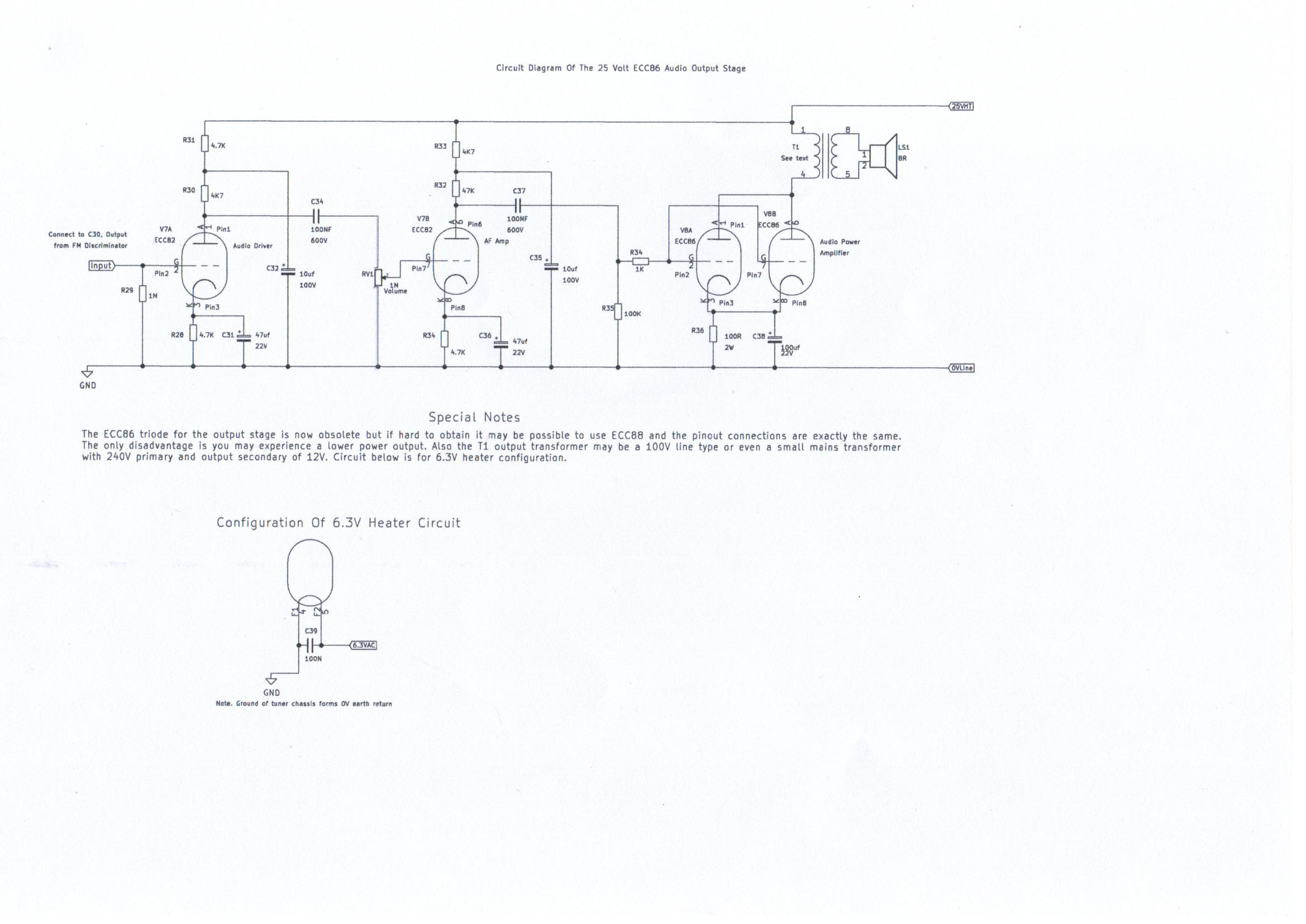
Alternative 25 Volt Optional Audio Amplifier using ECC86 Double Triode Valve
A new circuit based on the ECC86 double triode valve has been tried with great success as a low voltage power amplifier and as a result, it is now possible to obtain a decent 100 milliwatts of power using the same 25 Volt HT line as the tuner and will drive a speaker at very acceptable audio quality. More about this valve. The ECC86 was designed in the 50s as a VHF Mixer and oscillator in hybrid car radios using the space charge valve technique to eliminate the high voltage vibrator supply. It is capable of dispatching around 10 milliamps per triode using a 30V HT supply and is a framed grid valve similar to the ECC88 with its pin connections and heaters exactly the same. One word of warning. The ECC86 is not an substitute for the ECC88, particularly in the VHF Mixer of this tuner as past experiments revealed poor sensitivity compared to the original ECC88 configuration. Please refer to picture 11 which is the complete circuit and wiring diagram of this amplifier. The circuit for the driver stage uses the V7B half triode and pins 4 and 5 heater connections must be strapped together. Although the driver stage is the same circuit as used in the EL84 output stage, the HT supply to this stage must be connected to the regulated 25V HT line. The output stage has its triodes connected in parallel and is cathode biased at 0.68 volts to give a healthy anode current of around 7 milliamps resulting in low distortion. The HT supply to the output stage must route from the C1 reservoir capacitor positive connection of the power supply rather then the regulated supply for stability reasons and as with C1 having a capacitance of 1000 microfarads extra filtering is not necessary but could be a worthwhile improvement. The ECC86 at the time of writing is available from the following link Watford Valves and the output transformer is a 100 volt 2 watt line output transformer available from Maplin Electronics Code N85CC. This amplifier is more recommended then the present EL84 circuit and has a really loud volume for its low 25 volt supply which would have served well as a kitchen radio for listening to Tony Blackburn's Radio 2 Saturday morning show during breakfast in the 1960s.
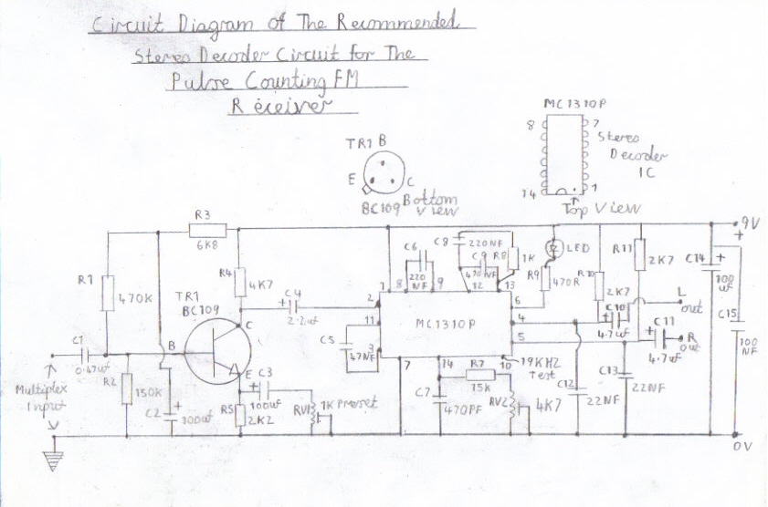
How to enable this tuner for stereo reception
Although this tuner gives very good clean mono reception with excellent sensitivity, you may wonder will this tuner work in glorious stereo. The answer is yes providing you have a decent antenna system and are lucky enough to live in a very good reception area, close to the transmitter site as possible with no hills or tall buildings within the signal path. The answer is no if you relie on using a short piece of wire which may work very well when receiving mono reception but may result in disappointing results when listening in stereo. I would like to warn you of the following problems you may find which I myself have experienced when testing this design for stereo reception. On the very strong stations it is capable of very good results with virtually no background hiss but the only disappointment I will comment on is if you are a Radio 3 listener you may experience slight background distortion in quiet passages of music accompanied with birdies which may not be apparent when listening to mono transmissions, so if this is your only favourite station then I would think very carefully before proceeding or have a switching circuit to re enable mono if the results are disappointing. Stereo reception also relies on a signal of at least in between 70 to 80 decibels for reliable hiss free reception and you need the best antenna system you can possibly go for, that is as high as possible and clear of buildings. The best antennas to go for are the 6 element yagibeam directional type which are sadly no longer available in UK local DIY shops due to the popularity of DAB digital radio which I will mention no further. Avoid the omidirectionl type that is rounded as these antennas tend to receive signals in all directions resulting in poor results even when receiving mono reception with multipath distortion. The modification required to the tuner is very simple and picture 12 explains how to modify the filter circuit in the FM demodulator which I will describe. C26 must be reduced to 100PF to recover the the 19KHZ pilot tone and 38KHZ subcarrier. You find after doing this modification the frequency response is a bit flat when not using the stereo decoder, so it may be worth incorporating a switching facility to change this capacitor back to its original value when not receiving stereo transmissions. You must also refer to picture 13 which is a phase correction circuit which must be connected between the tuner output and the stereo decoder multiplex input. The role of this circuit is to advance the S Signal components relative to the pilot tone giving an improvement in 30db stereo separation. Without this circuit the separation will be very poor due to the nature of the pulse counting detector and low 250KHZ IF frequency which has a low bandwidth compared to the usual 10.7 MHZ IF found in commercial manufactured tuners which is the main drawback of converting this sort of tuner to stereo regarding performance. Picture 14 is the recommended stereo decoder circuit for this tuner using the MC1310P IC and you must refer to the following link FM Stereo Decoder Circuit which has full information on how to set up this circuit. Please refer to the following instructions on how to adjust the phase correction circuit.
1. VR1 is the phase shift control and advancing this preset at zero resistance has no effect.
2. VR2 is an input attenuator and also helps higher the frequency response resulting in wider bandwidth required for successful decoding of stereo broadcasts
3. Advance VR2 at full resistance
4. Advance VR1 starting from zero resistance until separation improves
5. Advance VR2 very slowly in the low resistance direction and they may be even further improvement in separation.
6. All I can say for now is if all the above steps have gone OK with the setting up of this circuit is happy stereo listening.
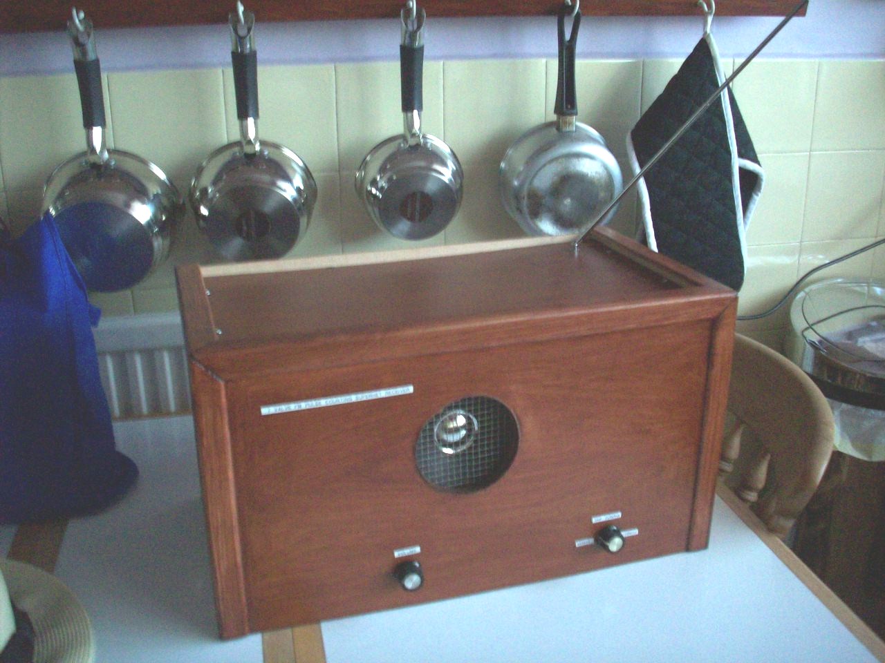
AM/FM Version Of The 7 Valve Pulse Counting Tuner
This is basically the same version of the low voltage VHF/FM version of the pulse counting superhet receiver but with a slight improvement in the IF amplifier circuitry and a separate frequency changer for the reception of Shortwave and Medium Wave broadcasts has been included. Also a simple ECL82/6BM8 Triode pentode valve serving as the preamplifier and audio power amplifier is also included saving the cost of an extra valve. Anyone lucky enough to still own the old style of record deck which were the BSR Monarch type autochangers incorporated in record players during the 1950s and 60s era are in for a pleasant surprise. The ceramic or crystal pickup head that were incorporated on these record decks will drive the high impedance input of the ECL82 triode with very pleasing output quality and decent volume. Also a phono preamp stage will be needed if the more modern Hi Fi turntables with the moving coil or magnetic cartridge is incorporated due to the lower impedance. A simple experimental circuit using an ECC88 triode has proved successful and will be included at a later date. Before I explain about the basic description of this later AM/FM Receiver project I want to briefly note the following point. Due to the inclusion of the AM Frequency Changer and slightly complex switching incorporated I am afraid to say that this later version of the receiver is not for anyone with limited experience or knowledge with RF circuitry or does not understand circuit diagrams. Also because the space of A4 paper is limited for composing complete circuit diagrams for this design, There will be no wiring diagrams for this project. On a good note of things anyone who has built my Severn Valve HF Superhet Receiver Designed For Advanced Constructors or read my following page 3 Valve Regenerative Superhet Receiver and at least had got that receiver circuit working successfully Should have no problem. It is the AM IF alignment that is the most difficult and as the RF Mixer and oscillator coils are not easily available I am afraid to say that it resorts to winding your own which are far more difficult then VHF coils to construct. The VHF alignment is the same as the FM only version and as the safety precautions still remain the same the AM alignment will only be explained. Please refer to the block diagram below for a description on how this later receiver works and the picture gallery for the circuit diagrams of each stage.
Block Diagram Of The 7 Valve AM/FM Version Of The Pulse Counting Receiver
|
|
|
|
|
|
|
|
||
Please left click on selected picture to enlarge image
Circuit Description of The AM/FM Pulse Counting Receiver
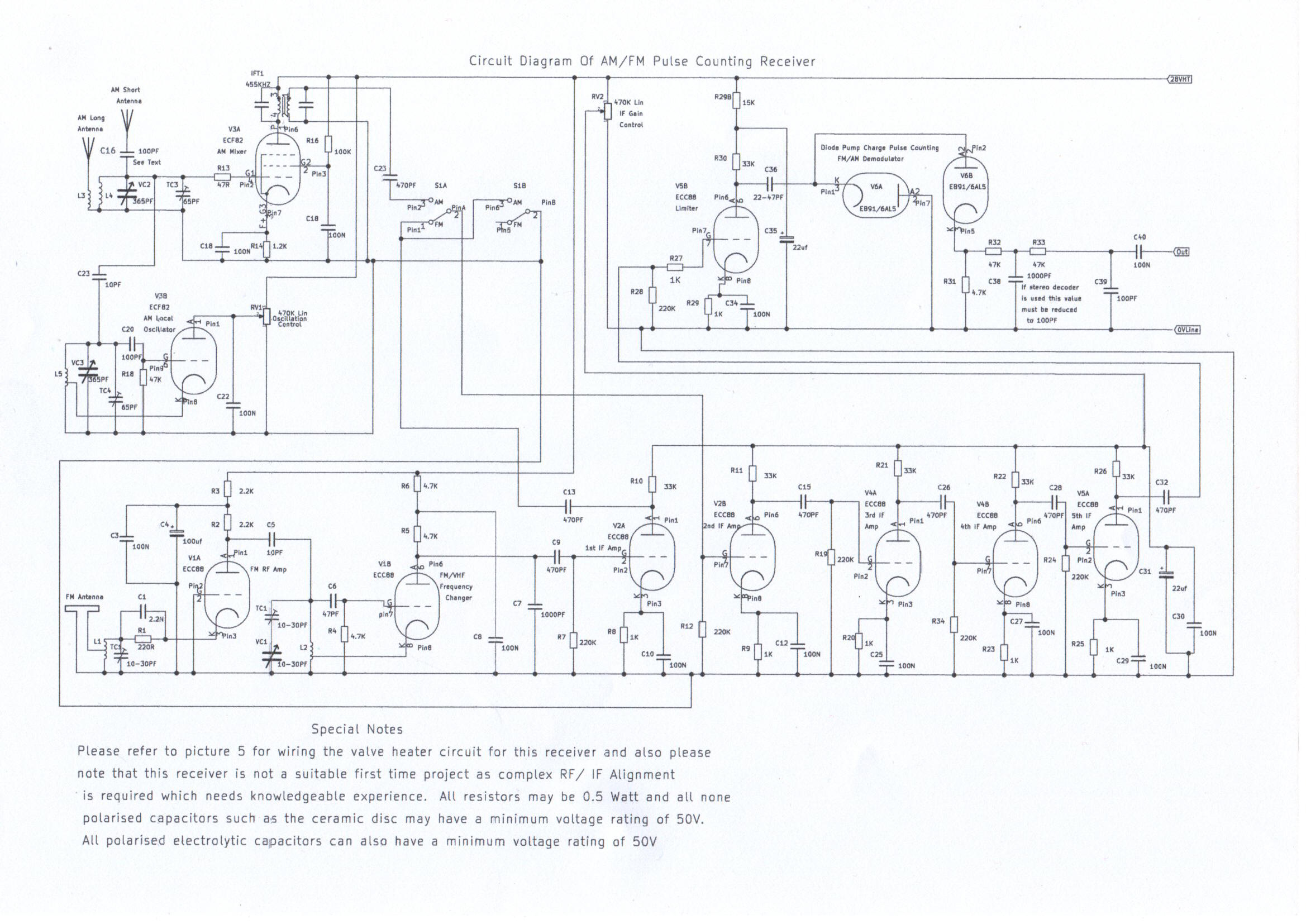
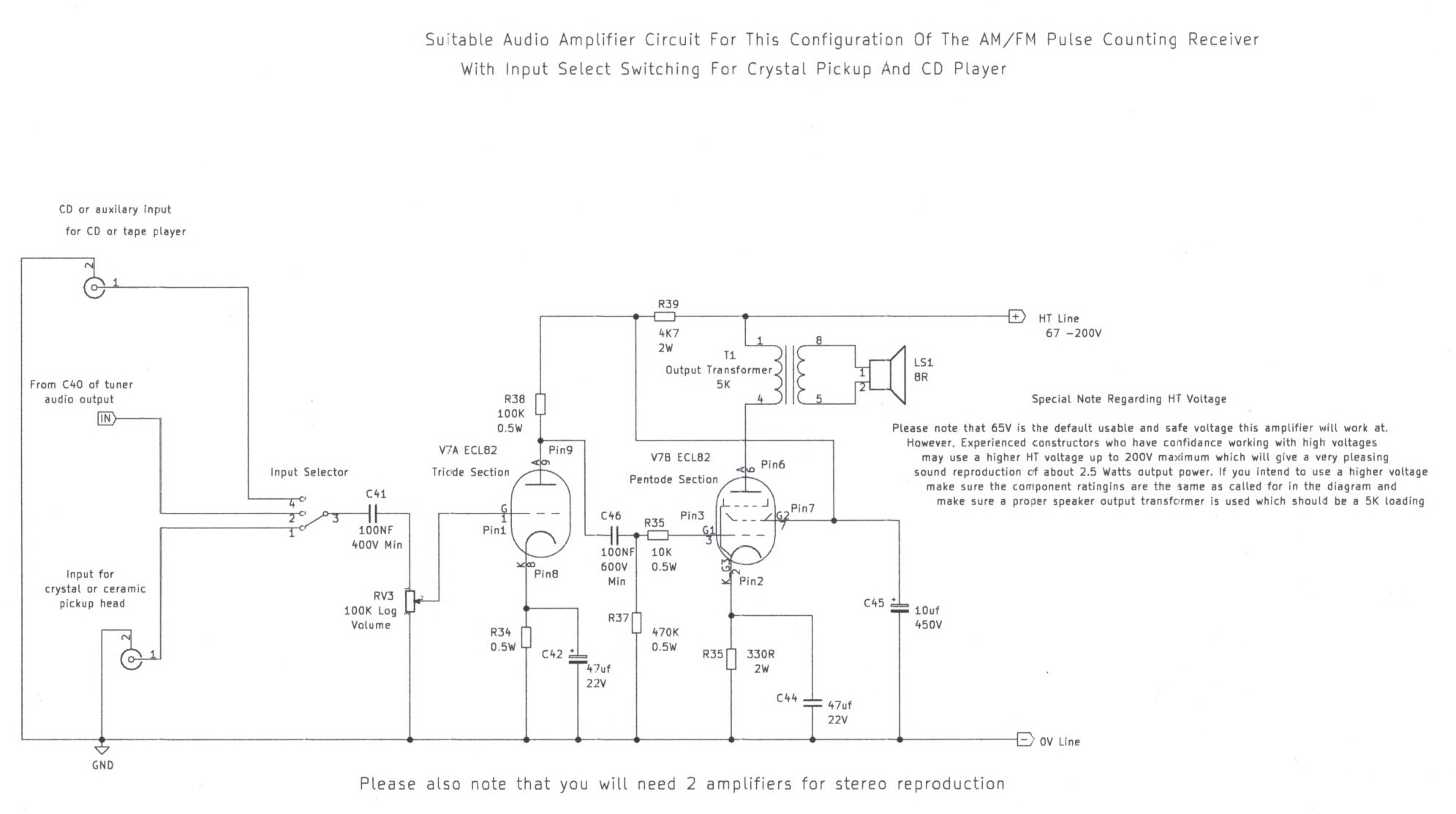
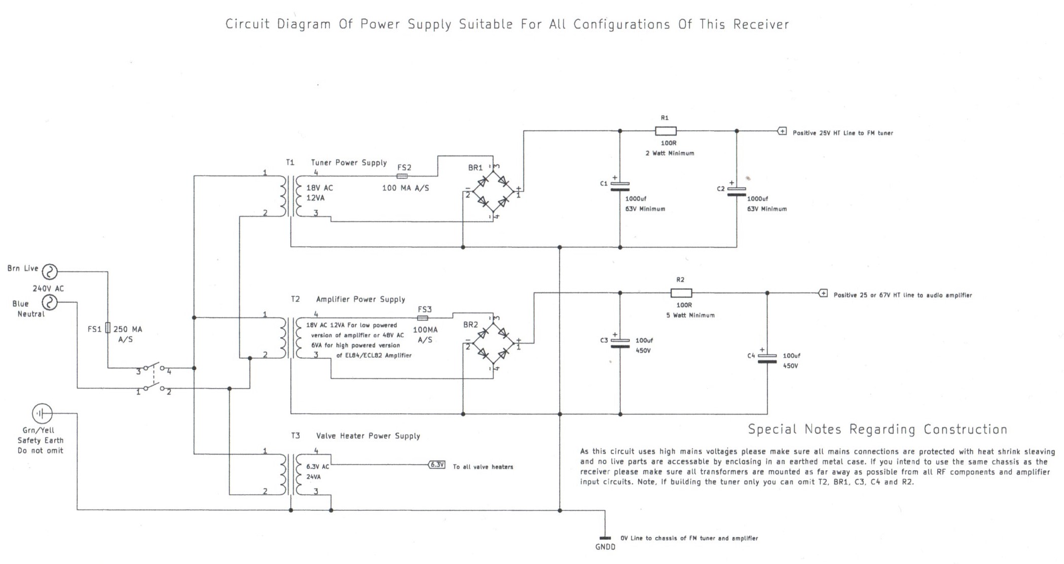
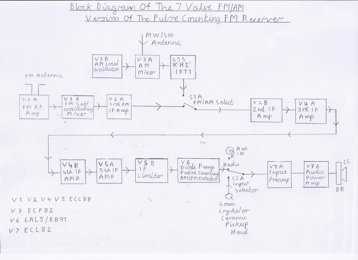
Referring to the block diagram, This version of the AM/FM valve pulse counting receiver works in the following order. You will also need to refer to picture 4 which is the circuit for the RF stages of this receiver design. V1A is tuned grounded grid VHF RF amplifier and its main purpose is to help isolate the VHF local oscillator from the antenna to minimize the possible risk of interference to nearby receivers. V1B is the VHF mixer and oscillator circuit consisting of the simple autodyne converter type circuit which works in the same way as described in the earlier FM only design. V2A is the first IF stage and you may wonder why it is configured for the VHF/FM section only which I will briefly describe. Firstly, FM needs a slightly stronger signal then AM and while experimenting I found that VHF Instability was a problem due to having the FM converter output in the AM/FM switching network of S1. The AM and FM switching works in the following manner. S1A is the main IF input selector which allows simple 1 pole switching to the AM 455KHZ IF output when Shortwave or AM Medium Wave is required. S2B is required for the simple reason which I will briefly describe. It was found that FM breakthrough due to the stray capacitive coupling of S1A was a serious problem when listening to AM so the purpose of S1B is to temporary short the FM IF output of V2A when AM is used. A brief note regarding this subject. Hot HT switching like the method used in my Solid State AM/FM Pulse Counting Receiver is not acceptable in this design as the risk of cathode poisoning of V2A would result due to no electron emission. V3 is a simple mixer and oscillator circuit for the reception of Shortwave and AM medium wave broadcasts which I will describe. It consists of the ECF82 Triode Pentode valve used in valved TV receivers of the 50s era and works very well at low HT voltages. The Pentode section serves as a simple mixer and the L4 Mixer tuned coil with VC2 in parallel is coupled to the control grid working in anode bend detection. The L3 coupling winding for the antenna is not essential when using short antennas but results in better selectivity when very long outdoor antennas are used and prevents damping of the tuned circuits due to signal overload and out of band signals. The triode section works as a separate local oscillator and cathode feedback is used resulting in easy construction of the L5 coils. The 470K RV1 preset regeneration control has been included for the following reason. It may be found due to ageing valves that the oscillator stops functioning when the receiver is tuned on the low broadcast bands when VC4 is at full capacitance due to lower cathode emission. The setting of this control can easily be found by trial and error. IFT1 is the 455KHZ Intermediate Frequency Transformer which the AM mixer is coupled too which I will describe next. V4A to V5A is the entire IF Amp Circuitry and although the purpose of the 470PF grid coupling capacitors C26 C28 and C32 set the frequency response to around 250KHZ, The bandwidth is wide enough to accept any frequency up to around 2 MHZ which in our case for the reception of AM we are using an Input frequency of 455KHZ formed by IFT1 and as a result we have a wide band 455KHZ IF amplifier. Although I may be describing solid state circuitry hear, This method is used with the ZN414 IC which formed the basis for a simple medium wave receiver or IF strip back in the early 70s except these ICs were only suitable for the detection of AM Signals. You need to refer to picture 5 which is the circuitry of the final IF stages. Because using AGC is a bit complicated to use in this design, The 470K RV2 potentiometer is a manual gain control and can be left adjusted to full potential when using FM. However, When using AM this control must be advanced between midway and full potential or severe distortion will result as the final detector V6 will be overloaded by a strong IF signal. V5B is the final IF valve and is also the FM limiter which works in saturation mode by using a lower anode voltage and its output is coupled to V6 which is a Diode pump charge detector for the detection of both AM/FM signals. One final note. This IF circuit works in the same way as the circuit in the earlier FM design but with slight circuit modification as I will briefly describe. The inclusion of cathode biasing each stage has resulted in better linear operation resulting in less distortion and interstation noise when tuning between FM stations. It is possible without this modification to modify the earlier FM version to an AM/FM configuration but please remember the statement I mentioned earlier about the complications that inexperienced constructors may face regarding the AM front end RF coils. V7 is the Audio amplifier stage and a simple circuit using the popular ECL82 Triode Pentode valve has been included. The ECL82 gives about 200 miliwatts when using a 56 to 65 volt HT line and will also give high output when using the amplifier alone with a crystal pickup. This particular circuit described in picture 6 was used in the Dancesett Major series of record players, Produced during the 1950s and early 60s era and is capable of very high quality reproduction. The power supply circuit in picture 7 is very simple regarding the low 25V HT required for this design. It was found that capacitive resistance smoothing works very well and you do not need to go to the expense of building the regulated circuit which is featured in the FM only design. Also the safety precautions remain the same as before except for the higher powered 2 Watt stereo version of the ECL82 Amplifier which I will briefly explain. This version of the amplifier uses a lethal 260 Volt HT line and on no account should be constructed if you are unsure of your experiences with high voltages. If you are in any doubt then my advice is do not even attempt the construction of this receiver project. NB Important note regarding the RV3 volume control on ECL82 Amplifier input stage. The present value 100K is OK for feeding input sources such as CD Players or the sound card output of a computer. To archive maximum output when using the AM/FM tuner you will need to increase this value to 1M which will also result in better bass response. This modification is also essential when using a Crystal Pickup and will also even result in better bass response with more open sound reproduction when using CD players.
General Construction Details
Before proceeding with the construction of this version of the AM/FM receiver please refer to the components list by clicking on the following link Components List Of 6 Valve VHF/FM Tuner . Except for The AM/Shortwave section of this receiver please refer to the earlier construction details relating to the 6 Valve FM only version as the alignment is exactly the same.
AM/Shortwave Coil Construction
There is good news regarding the construction of Shortwave coils for this receiver. As tracking precisely with the mixer and oscillator is not as critical they can both be constructed in the same way as you do with constructing regenerative receivers and the turns on the tuned windings can remain the same. The Medium Wave coils are very critical and I myself have not found very easy and resorted to a lot of guess work regarding the oscillator coil construction. The problem lies with precise tracking alignment as frequencies get lower and if not done correctly you will find performance on the low end of the Medium wave band very poor with instability and lack of sensitivity. Also there is not a lot of the late night Pop music stations that used to be in big numbers as long ago as the mid 1990s due to lack of funding and electrical interference from cathode-ray computer monitors and switch mode power supplies is now a big problem which due to this has seen a decline in listening audience over recent years. If your interest resorts to medium wave listening the following link http://www.angelfire.com/electronic/funwithtubes/Coils-1.html has full details relating to the construction of Medium wave RF Antenna and Oscillator coils. If your interest is mainly Short wave listening please refer to picture 8 which is a diagram explaining the full physical details and resort to the simple table below regarding the band concerned.
SW1 5.5 MHZ to 14.0 MHZ
Both RF Antenna and oscillator coils are wound separately on 15 X 50 mm plastic tube and 20 SWG enamelled copper wire is used.
L3 Antenna coupling coil- 4 turns.
L4 RF Antenna Coil- 10 turns with turns wound in opposite direction of L3.
L5 Oscillator Coil- 10 turns with cathode feedback tap wound about 3.5 turns from the earthy end.
SW2 1.0 MHZ to 4.5 MHZ
Both RF Antenna and oscillator coils are wound on 15 X 70 mm plastic tube and 36 SWG enamelled copper wire is used
L3 Antenna coupling coil- 15 turns.
L4 Antenna coil- 60 turns wound in opposite direction of L3.
L5 Oscillator coil- 60 turns with cathode feedback tap wound at about 10 to 15 turns from earthy end
IFT 1 IF Transformer
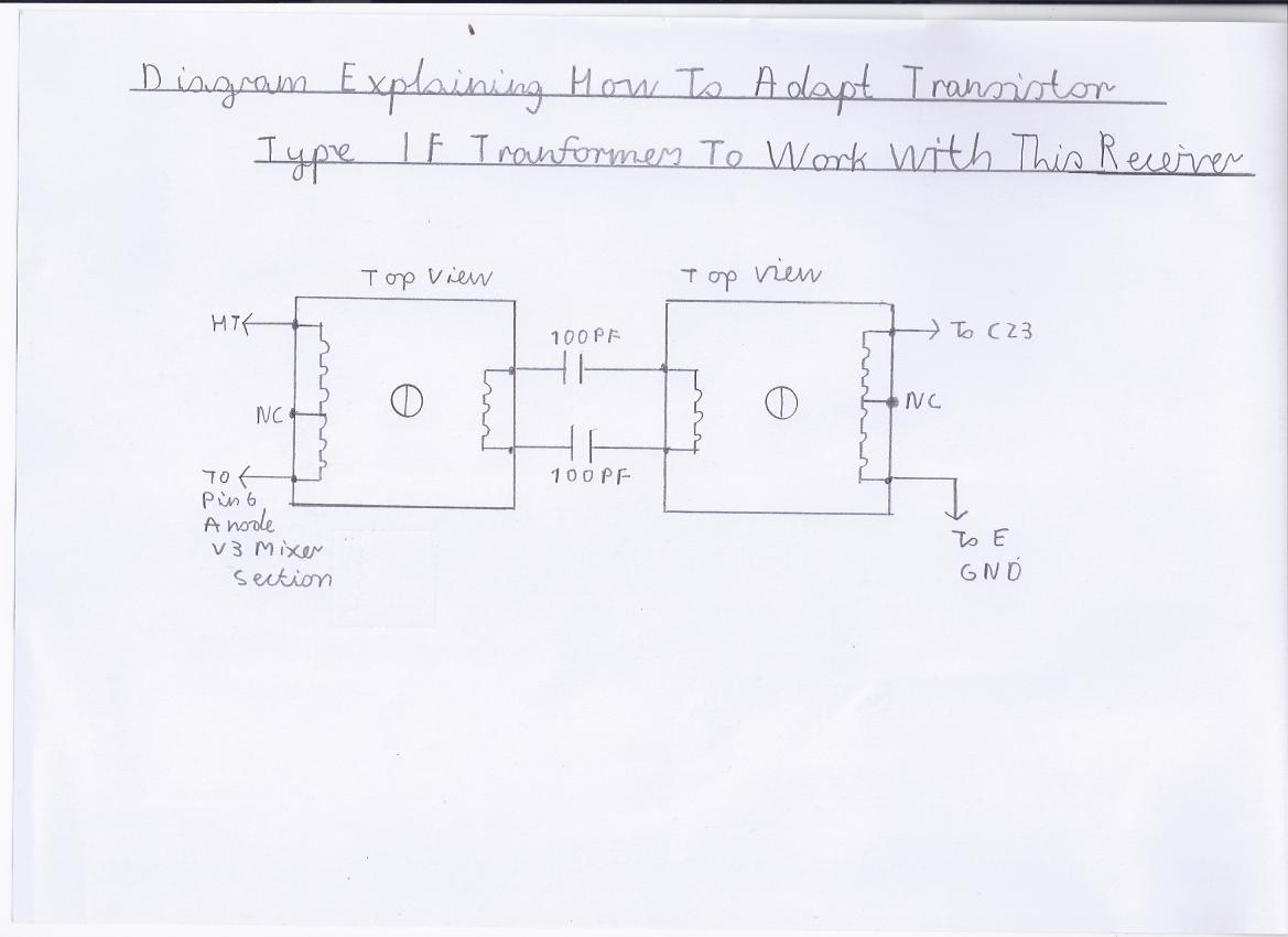
There is good news if you have an old valve radio that is out of commission. Any of the IF 455KHZ or 470KHZ transformers will be suitable and as the windings are double tuned, They can be connected ether way round. If this is not the case then you will have have to use 2 transistor type IF transformers with there low impedance windings connected back to back. Picture 9 explains how this is done and the 100PF ceramic disc coupling capacitors have been included for the following reason. It was found on the prototype version that these windings are easily burnt out due to there thinness. Not only will these transformers burn out in valve receivers that use a 250V HT Line, They can't even stand a 25 Volt HT Line. The Ceramic disc capacitors must also have a minimum rating of 50 Volts.
AM/ Shortwave Mixer Alignment
I will start with the medium wave alignment first as it easier to be familiar with stations on that tuning range if you listen on those frequencies mostly and will make alignment very easy. Because there is only 1 IF transformer involved in this design, There is no complex IF alignment to worry about and if you are using valve type transformers you can simply leave them as they are because there will be no difference when peaking the core for maximum sensitivity other then slightly altering the tuning range. If using transistor type IF transformers you will probably have to peak both of them for maximum sensitivity. When aligning the shortwave frequencies an RF signal generator will make adjusting the tuning range more easier particularly if you are not a regular shortwave listener as you will be less familiar with the band layout. Please refer to the following steps for medium wave alignment.
1. Switch the receiver on with the AF volume control set between mid to maximum volume and allow the valves to warm up from about 5 to 10 minuits to ensure correct oscillator alignment.
2. If you have currently got the receiver switched to the FM mode, Make sure the IF gain control RV2 is set to maximum gain by advancing this control fully clockwise.
3. Switch the receiver over to the AM mode and connect about 2 metres of insulated wire to the short antenna terminal.
4. Try tuning in any strong AM station preferably at the top frequency end of the medium wave range such as Absolute Radio which broadcasts on 1215 KHZ.
5. If reception sounds unintelligible and distorted, Try advancing the RV2 IF gain control anticlockwise maintaining this control very slowly until the station sounds more clearer with no distortion.
6. Adjust the TC3 antenna trimmer for maximum sensitivity and if the signal starts to distort you need to repeat step 5.
7. If all has gone alright with the the last procedure, Try tuning in a station at the lower end of the frequency range such as UK Five Live which is broadcast on 693KHZ.
8. You may find that the local oscillator drops out as you get lower in frequency and by advancing the RV2 Oscillator regeneration control slowly clockwise, This procedure should should correct this issue.
9. If stations at the lower end of the frequency range seem a bit weak then you need to readjust the RV2 IF gain control in the clockwise direction to correct this problem and readjust the TC3 antenna trimmer for maximum sensitivity. If you then start to experience distortion or excessive overload of signals you need to repeat step 5 to correct this.
10. A word of caution regarding antenna connections. The long antenna terminal is more recommended if you happen to have a very long outdoor antenna set up as connecting a long antenna directly to the short antenna terminal will overload the mixer as well as the receiver experiencing other spurious responses such as out of band signals. Also replacing C16 with a 10 to 100PF trimmer on the short antenna terminal may also improve selectivity by reducing the capacitance and should also form as an ATU Antenna tuning unit which will also match the antenna more efficiently.
11. The oscillator trimmer TC4 corrects the tuning range as follows. Closing the vanes of TC4 lowers the frequency coverage and you may have to carry out this procedure if you experience extended high frequency coverage when tuning on the lower range of the band in question. The opposite procedure is true if you find you are lacking high frequency coverage on the high frequency end of the medium wave band, Which in that case you need to open the vanes very slowly to correct this issue. Also using a known working medium wave receiver will help you correct alignment particularly during the evenings when strong continental stations are more easy to identify.
12. Shortwave alignment is very much the same except you need a known working shortwave receiver to assist you in identifying the correct frequency alignment and it will require a lot of patients which in this case if you do happen to have access to an RF Signal Generator this will make things a lot more easier.
13. A final word to those who wish to incorporate band switching of the AM Medium and shortwave tuning range. It is done in very much the same way as the Regenerative receivers elsewhere on this website such as the Simple Radio Receiver Circuits For Beginners except please note the following points. As you have four windings to switch in the RF frequency coils, The risk of poor performance and instability is very high unless the following points are observed. You must ensure that the wiring in the circuit layout is kept as short as possible with no dry solder joints and you must make sure that the high frequency coils have the shortest lead connections to the band switch. Also separate trimmers for each band coil will also be required. Also as a final reminder, Do not try to add band switching in the 88 to 108 MHZ VHF/FM Range. If you attempt to do this, You may get all the lower frequencies working spot on but due to the loses in the switch and circuit leads you will experience excessive tuning drift and lack of coverage on the high frequency end of the FM band. Also this is the reason why a separate frequency converter has to be incorporated when designing an AM/FM configuration of this type of receiver. A circuit for band switching will be included at a later date.
Finally
I am pleased to say that a lot of work and effort has gone into composing these 2 versions of the valve pulse counting FM Receiver and I hope you enjoy building and using them. I will be taking a well earned break from this side of receiver projects at least for the time being as I have got a lot of other unfinished projects and household jobs to finish off. Also due to a 5 day 39 hour full time work schedule, This limits my time as well as leisure.
Video Clips of These Receivers Working
Phil's design of a valve FM pulse counting tuner using safe 25 volt HT line- YouTube
Experimental FM Medium And Short Wave Version Of The Valve Pulse Counting Receiver.MP4 - YouTube
Links To My Other FM Receiver And Hi Fi Related Projects
Valve Version Of The 10.7 MHZ Double Conversion VHF/FM Pulse Counting Tuner
Transistor Pulse Counting FM Receiver
Double Conversion Pulse Counting FM Superhet Receiver With 10.7 MHZ First IF Stage
Single Conversion 6 Transistor 10.7 MHZ Pulse Counting Receiver, Designed For Stereo FM Reception
Solid State AM/FM Pulse Counting Receiver
3 Valve 3 Watt Stereo Amplifier
Simple Stereo Preamplifier Circuits For The 3 Valve Stereo Amplifier
Site Map Of All My Webpages And Favourite Valve Radio Related Links