Simple 2 Valve Regenerative Receiver
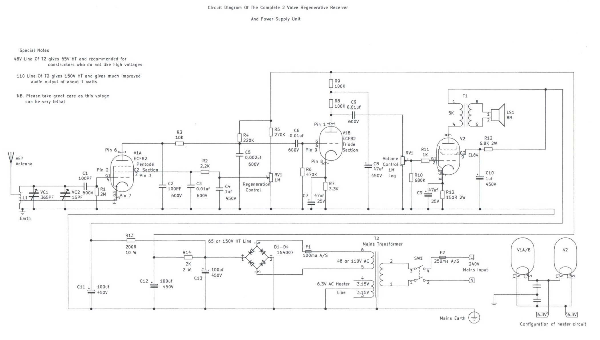
Basic Circuit Diagram Of 2 Valve Regenerative Receiver
|
|
|
|
|
Please left click on selected pictures to enlarge image
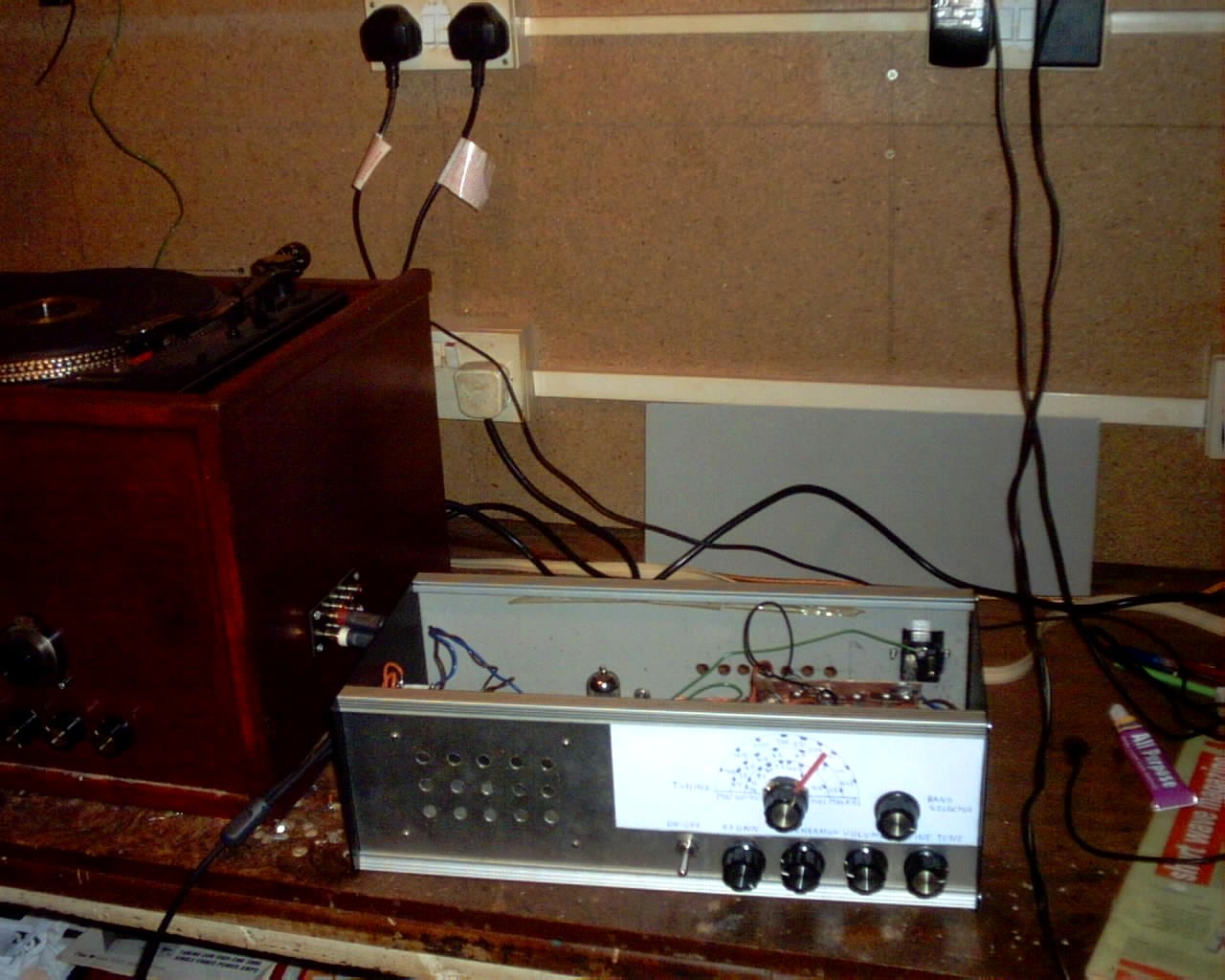
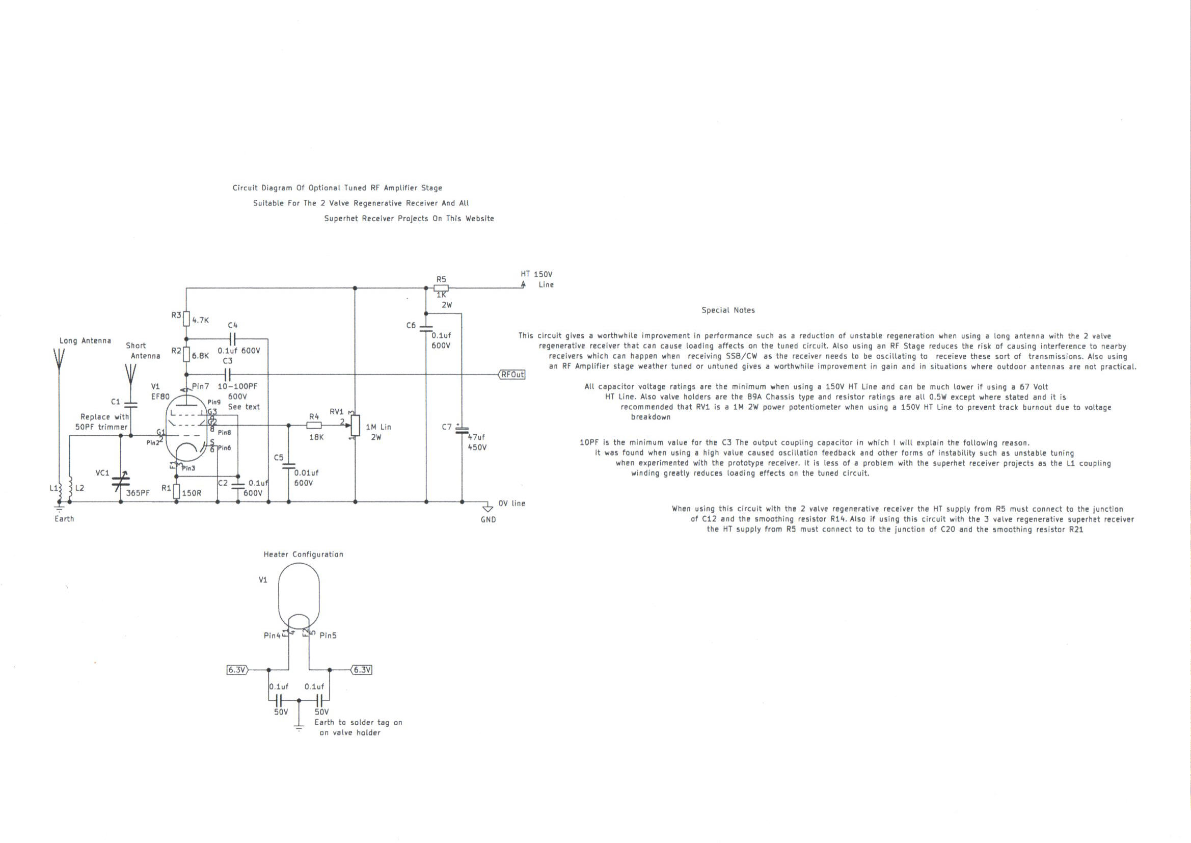
Welcome to this part of my site featuring construction details on how to build one of the simplest valve radio's, capable of driving a speaker at decent volume. Although not suitable for an absolute beginner to electronics, as it involves using mains electricity for its power supply. However, It is suitable for anyone who can read and understand circuit diagrams and has at least had experience with building mains powered projects. The good news about this design is it will work well with a low HT voltage of only 65 volts, with a audio output power of about 250 milliwatts. The circuit description for the radio stage is as follows. V1a, the pentode section of this valve is a simple leaky grid regenerative detector, consisting of L1 and VC1/2 for the tuned circuit, using cathode feedback which makes the construction of the aerial coils very simple. RV1 is the regeneration control and this is one of the drawbacks of this kind of receiver, as it needs to be readjusted when tuning from one end of the band to the other. V2b, the triode section is a simple voltage amplifier, providing plenty of gain to drive the EL84 output stage with RV2 as the volume control. The valves used in this receiver are as follows. V1a and V1b are two valves combined in one glass envelope consisting of the ECF82 triode pentode, an excellent little valve used in TV and Radio Receivers during the valve era in the 1950s. V2 is a EL84 output valve and was also used in many record players and amplifiers of that era. I will describe the following important points to remember about this type of receiver. Do not expect to get the same performance of what you get, regarding selectivity as you would from a superhet design. This is due to using one simple tuned circuit, making the separation of stations difficult, particularly on the high end of the medium wave band, after dark. Also these sets give best sensitivity when the regeneration control is set just before the set brakes into oscillation. Unless you are listening to CW or SSB single sideband transmissions, do not allow the set to oscillate continuously when using the broadcast bands, as it is possible to interfere with nearby sets over a considerable distance. Aerial coupling may also present a problem, causing damping of the tuned circuits and regeneration, which can be eliminated by using an additional RF stage which full details are now provided in the construction article. The Power supply is a very simple affair using a resistance capacitor input filter, with bridge rectifier and transformer for the 65 Volt HT and 6.3V for the valve heaters. It is also possible to use a higher voltage of about 150V HT maximum for a output power of about 2 Watts, Provided the components are properly rated and safety guidelines regarding high voltages are taken into consideration. Please bear the following note if you are planning to upgrade your existing design of this receiver to my newly featured Severn Valve HF Superhet Receiver Designed For Advanced Constructors The EL84 AF Amplifier is the same design and can be retained. The EF 91 RF Amplifier is also the same and needs no further comment other then it must follow the ECF 82 Mixer valve. The power supply uses Choke smoothing and calls for a redesign of the current power supply of this design. The following details are featured in the 5th picture and the circuit will also give better performance for this design, Resulting in low mains hum and better regulation. I am now pleased to say there is a video clip of this receiver working with the optional RF Stage and can be found at the following web address YouTube - My 3 Valve TRF Regenerative HF Receiver.MP4 .
Links To My Other HF Shortwave And Medium Wave Receiver Projects
3 Valve Regenerative Superhet Receiver
Severn Valve HF Superhet Receiver Designed For Advanced Constructors
Solid State AM/FM Pulse Counting Receiver
Simple (ATU) Antenna Tuning Unit For All HF Receiver Projects
Site Map Of All My Webpages And Favourite Valve Radio Related Links