3 Valve 3 Watt Stereo Amplifier
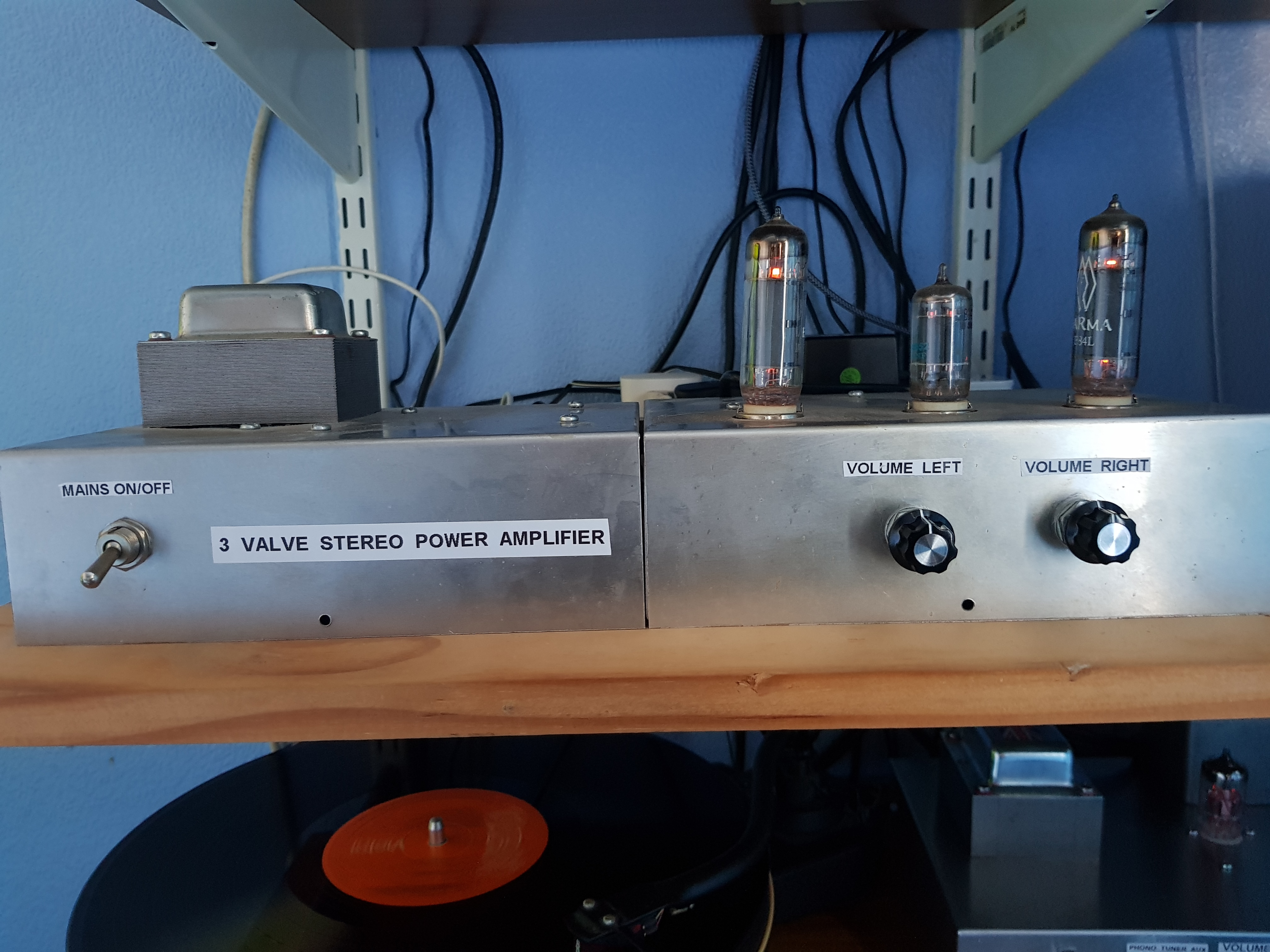
Picture Of The Prototype 3 Watt Stereo Amplifier Used In My Workshop Simple Hi Fi System
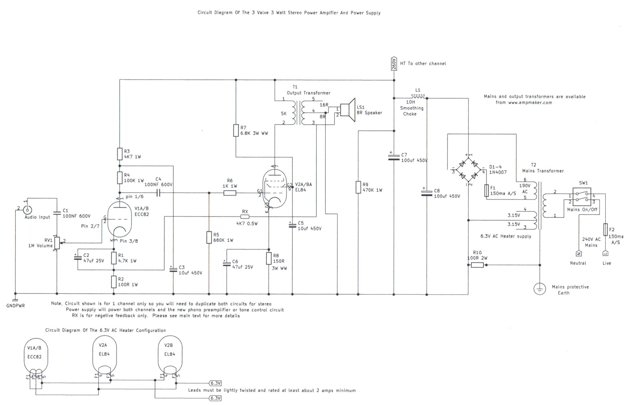
This part of my site features construction details of an easy to build 3 Watt Stereo amplifier using basically 3 valves to form a low powered Hi Fi amplifier suitable for use in a normal sized living room without having to spend between £400 to the cost of a new house or car for the following obvious reasons. Many modern valve amplifiers are designed with appearance in mind regarding the chassis and it usually consists of high quality stainless steel, Galvanised in gold chrome which adds up to half the expense of the amplifier. Also the component quality has a lot do with it such as they love to choose the best quality components which add up to this expense. The list of expensive components can be endless from mains transformers to signal cable and yet the amplifier will sound no better then a design made at lower cost which I will briefly explain. Keeping the cost low without the amplifier suffering from reliability and poor performance issues depends on the following factors. The mains transformer is the most important component to take in to consideration for the obvious reason. Like the human heart pumps blood around your entire body, The mains transformer does the same thing electrically and it must be able to do this without getting stressed which means not allowing it to get too hot which can lead to overheating and it is this problem that many amateur constructors cut the corners with by going for the lowest cost possible which is simply purchasing one that will just give the maximum HT current and heater requirements in which after a period of time leads to problems such as overloading eventually leading to burn out. Another problem that is also overlooked is the signal output coupling capacitors which couple the control grids of the output stage in which I will explain. This component must be at least twice the HT voltage of the amplifier and of the very high quality polypropylene type because if this component becomes leaky with only as little as 2 volts on the control grids of the output valves, You may if this problem is not immediately noticed face an expensive repair on your hands. Why does this happen you may ask yourself ? In the case of this amplifier each EL84 output valve is designed to run at 0.048 ma power disputation which with a 250V HT supply gives about 12 watts and is the comfortable maximum power this valve will handle. The voltage on the cathode resistor in this case should read about 7.2 Volts which up to now everything may seem to be hunky dory but due to the fault of the coupling capacitor suddenly becoming leaky and as a result this voltage increases to 9.2V ? With this new grid bias voltage the output valve will see an anode disputation of about 0.061 ma which is a power increase of 3 watts adding up to 15 watts. If the amplifier is used in this state over a period of time the increase in anode current will damage the valve resulting in melting of the anode and eventually the output transformer may fail. Also if the HT output is not fused tightly, The rectifier and mains transformer may also fail. This trouble is caused by the simple error of using an under rated voltage or leaky coupling capacitor which with common sense can be avoided by careful component choice. An experienced valve amplifier technician can easily spot signs of leaky coupling capacitors as I will briefly explain. The original sound will be muffled with distortion even at low volume levels and the output valve anodes will have a cherry red glow. More on this subject will be mentioned in the safety precautions section later. Also in a domestic 3 bedroomed semi detached house you do not need an output power of 100 watts or even as high as 20 watts to get decent quality volume or high fidelity reproduction which I will explain the key factor to achieving this. Any amplifier as good as it claims to be will give poor quality reproduction if the speakers are of poor quality and these components are worth spending a bit of expense on as the ones from your old 1980s transistorised music centre will be of the cheap single cone units which are not strictly speaking hi fi quality. More on this design and the circuit description. This design uses a minimum of just 3 valves and is of the single ended type using the standard EL84 output stage which was popular in many radios and record players of the 1950s and 60s era. The signal input stage consists of a simple double triode ECC82 voltage amplifier in which each half triode shares both channels. Negative feedback is used to reduce distortion at high volumes resulting in better fidelity. Also depending on the size and quality of speaker, The amplifier works very well without negative feedback. The power supply uses solid state bridge rectification and choke smoothing has also been included resulting in better regulation and as a result the hum level is very low. Also an isolated power supply with no transformerless techniques is used which reduces the risk of shook hazards when connecting ancillary equipment such as an FM tuner or Phono Preamplifier to the signal input and that also includes all the radio circuits on this entire website. This amplifier is very easy to construct and set up and anyone who has had experience in building the valve FM receiver projects should have no problem but please read the following reminder concerning safety. This amplifier uses a lethal HT line of 250v DC and as a result it is not suitable for complete newcomers to build. Having said that if this design is built correctly using the recommended components it should give you many years of listening pleasure. Have Fun. Important announcement regarding updates to this page. As you may have noticed I am gradually updating all pages on this site with higher quality circuit diagrams as part of the 2021 revamp. All hand drawn diagrams are being removed and as a result, You will until I can find a suitable tool for drawing the layout wiring diagrams have to refer to the circuit schematic diagram and text before thinking about construction. As you can see the first picture is an example.
|
|
|
|
|
|
|
|
|
|
Please left click on selected picture to enlarge image
Important Safety Advice And The Simple Do And Don'ts With High Powered Valve Amplifiers
Valve amplifiers apart from all the extensive chassis metal cutting are easy to wire up and in fact easier then high power transistor amplifiers to build as there is no need for heatsinking to mount or extensive setting up like having to set the bias currents particularly if you build this sort of design which simply uses automatic cathode biasing. Having said that, High power valve amplifiers are not suitable for any constructor who has never had any experience with building mains powered projects or does not have any knowledge of the dangers high DC voltages present for the following reasons. The DC output voltage required to power this amplifier is much higher then the voltages used in all my other radio and amplifier circuits consisting of 250V DC. This voltage can kill if accidental contact is made and as it is of DC direct current, Your hands or fingers can become locked to the circuit without being able to let go eventually leading to cardiac arrest of the heart which can be fatal. Also the smoothing electrolytic capacitors may hold a lethal charge when the amplifier is switched off and unplugged from the mains in which a safety discharge resistor has been included to help take care of this but it may take around 10 minuits to completely discharge. For the previous safety warnings explained you must make sure this amplifier is built in a solid aluminium chassis that is soundly earthed and no live connectors or components can become accessible to the user. Valve amplifiers also run very warm after a period of moderate use and for this reason you must allow plenty of ventilation to avoid overheating. For example they must be installed in an area of the room where no direct sunlight exists and not in an alcove or under a bookshelf. Also there is another important consideration regarding this issue if you intend to use your amplifier in the living room where children or pets may be present. Valves run very hot and as a result they can burn if accidently touched so make sure you install your amplifier so it is not easily accessible to small children or pets. It may be also be strongly recommended to install a protective wire cage to put over the top which will ensure maximum safety as young children may not fully understand the dangers. As this design only incorporates 3 valves it is possible to have this amplifier installed in a cabinet as a record player or radio gram setup similar to the 1950s era providing it is properly ventilated and no live parts are accessible. There is 1 more important precaution that must always be followed regarding the installation of a valve amplifier and that concerns the speaker output connections. As many solid state constructers may tell you, A transistor amplifier does not like a short circuit load and can lead to rapid destruction of the output transistors if left in this sort of state for too long. One of the most common mistakes amateurs make is they do silly things such as connecting 2 X 8 ohm speakers in parallel to the output which then sees a new load of 4 ohms and over a period of time this will overload the output stage due to the fact that it is strictly designed to be used with an 8 ohm load. A valve amplifier is opposite for the following reason. Operating a valve amplifier with an open circuit load on the output can burn out your output transformer and overstress the output valve if left in the following state for as long as half a minute for the following reason. In the case of this amplifier, The output transformer must see a primary load of 5200 Ohms with an 8 Ohm speaker connected which forms a complete continues link only separated by speaker cables. Without this load the back emf electromagnetic force will be reflected back into the primary which in turn will see a heavier then usual current and as a result this condition may lead to burn out and failure of both the transformer and output valves. In the case of this amplifier the output transformer also has multiple output tapings for speaker loads of 4 to 16 ohms. Using an incorrect tapping will not burn out the output transformer immediately but you may ether experience a lower output then usual and the sound quality may sound a bit dull due to an unmatched loading. On a closing note, I hope this long list of precautions do not scare you off building this wonderful project and providing the recommended components are used this amplifier apart from having the odd valve too replace will give you years of trouble free service.
General Construction Of The 3Valve Stereo Amplifier
Before attempting the construction of this project please refer to the following link Components List Of 3 Valve Stereo Amplifier which gives you full details of all the recommended components and it is best to make sure you have the full availability before commencing with construction. This amplifier is constructed in the same manner as a valve amplifier kit that Maplin Electronics introduced as a low cost project during the early 1990s that was discontinued a long time ago. It was based on the popular Mullard 20 Watt design introduced in the 1950s. To spread the cost for people that were on a low budget you could build the power supply and amplifier by ether buying the 2 complete kits or buying the parts as you build. This design is of similar construction in that it has a separate chassis for the power supply and amplifier joined together by metal bridging straps or a front panel of ether aluminium or strong wood pine finish wood can be used for even better front appearance. One of the obvious reasons the chassis is constructed this way is because a suitable chassis size is not easy to buy off the shelf to accommodate everything like it used to be the case during the valve era, Although experienced constructors may make there own if they are lucky enough to possess a gelatine or other sort of metal bending machine. Just a final reminder before you decide to go ahead with the construction of this amplifier. If you have managed to successfully construct projects on the same level of My featured 6 Valve VHF/FM Pulse Counting FM Tuner Using Safe 25Volt DC HT Line and its add on EL84 amplifier circuit then you should have no difficulty but please bear in mind the warnings previously mentioned. It requires a lethal high voltage of 250V DC which is not suitable for inexperienced constructors so if you feel you are not confidant with high voltages do not even think of attempting the construction of this project. Remember you are taking your own risk.
Preparing The Chassis And Component Assembly
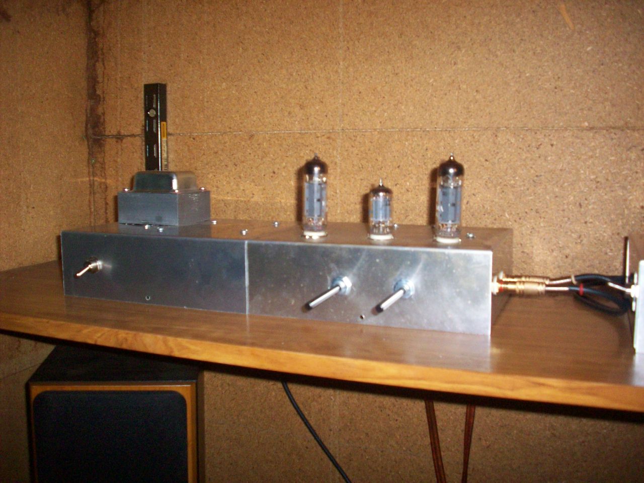
Picture 3 is the recommended component layout weather you are using your own chassis or the 2 AC86 Maplin chassis strapped together and it is the under view of the chassis. The only hard cut out to do is the recommended rectangular hole for the mains transformer which should be proceeded with first before familiarising yourself with all the rest of the chassis mounted components to give you a good idea of all the drilling requirements needed regarding hole sizes. After all chassis cutting is done all components should be mounted before the wiring is carried out. Also, To avoid metal debris that can lead to short circuits do not drill and then wire various parts of the amplifier as you go along because this does not as you may be lead to believe the best way of spreading your time and can lead to costly mistakes later. It is also best to organize the hole drilling for the power supply smoothing circuit board as this is also a chassis mounting item and you must make sure you use spacers that gives this board at least 5mm clearance to avoid short circuits. You must also make sure you use the 4 Red fibre mounted washers provided with the mains transformer and are mounted on the top of the core to prevent each bolt acting as a short circuit turn. The mounting of the 2 output transformers shown in picture 3 in a triangular fashion may confuse you but was done on the prototype version because the chassis only has just enough room to just accommodate them. The power supply is the first item to wire up and test before wiring up each amplifier channel and will follow next.
Wiring Up And Testing The Power Supply
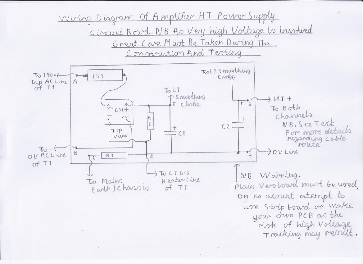
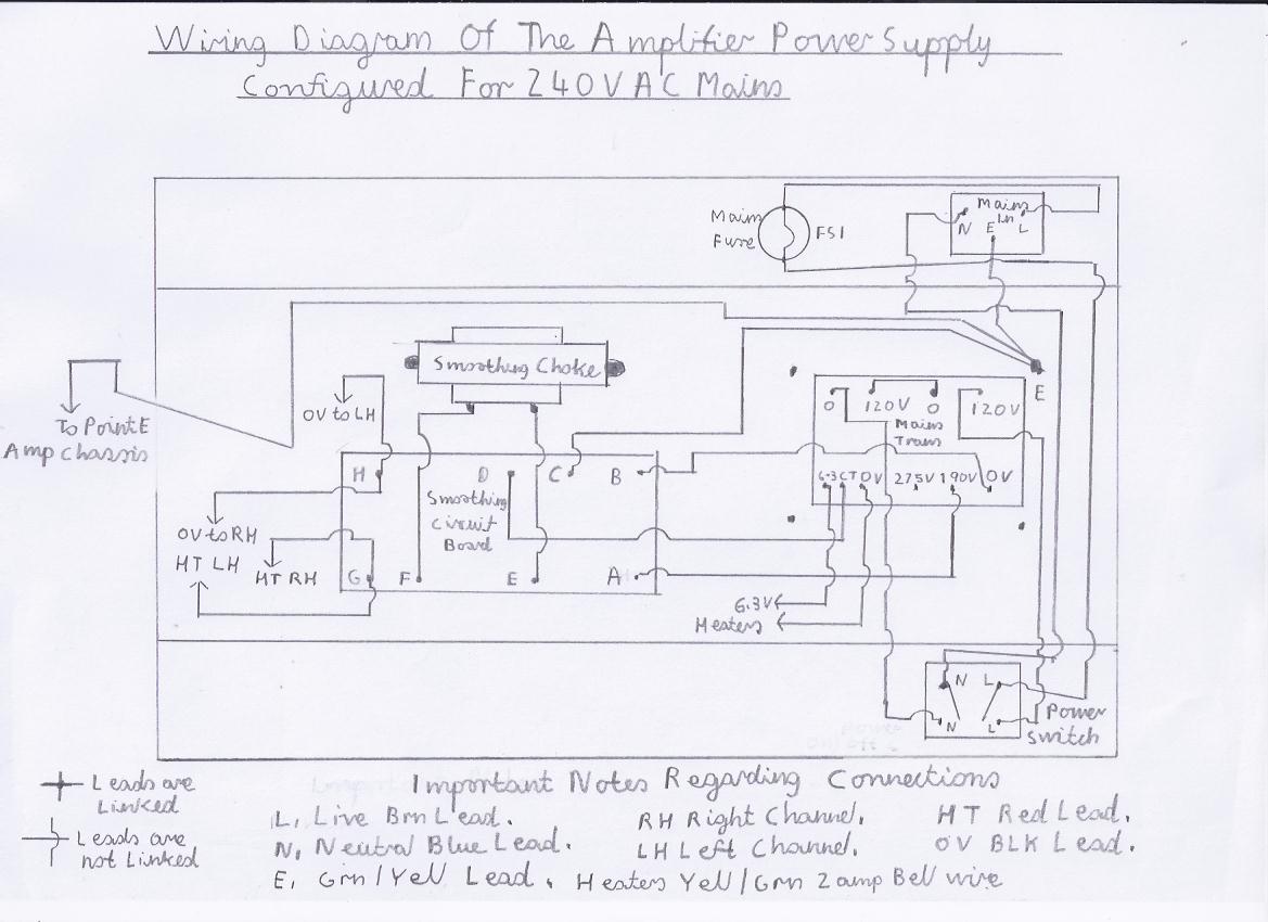
You need to refer to picture 1 the circuit diagram and picture 5 for the wiring diagram. You also need to refer to picture 4 for the wiring diagram of the smoothing circuit board. Take note that the smoothing circuit board has alphabetical labelling for its connections to make identification easy but always check your work against the circuit diagram and make sure you fully understand how to read it. Before you proceed with the wiring you must take note of these following important safety precaution steps as you are now dealing with a lethal voltage of 250V DC and any serious error could result in fatal electric shock or expensive damage.
1. You must when testing make sure you work with the one hand in pocket procedure and make sure your test meter is capable of reading at least 500 to 1000V for this project. The test probes must also be soundly insulated with no sign of bare strands or damaged insulation.
2. Do not use any antistatic whist straps or mats as valve projects do not need any antistatic precautions and there use could result in a fatal earth loop shock.
3. Please read these following precautions regarding safety with the Electrolytic smoothing capacitors and that includes all the decoupling bypass electrolytic capacitors within the entire amplifier. You must make sure they are connected in the correct polarity as shown in the wiring diagram or they may explode with a spectacular firework display which can also be very dangerous. The Plus + sign must always correspond as shown in the circuit and wiring diagram in the correct orientation. Also these capacitors carry a lethal charge long after the amplifier has been switched off and R2 is a safety discharge resistor that gradually discharges these capacitors to a safe level when the amplifier has been switched off but you must double check with your test meter to make sure this really happens. More on this procedure will be described in the testing and setting up.
4. The mains and HT fuses provide essential protection against any fault resulting in a heavy current overload which can be due to faulty or aging output valves, Capacitor and bridge rectifier failure. You must always make sure these fuses are of the correct rating as shown in the text and do not use any foreign substitute such as tin foil or you may burn out your mains and output transformers. Also there could be a serious fire risk and if these fuses are repeatingly blowing there is a serious fault that must be investigated before carrying on any further. As you may also notice in this design the HT fuse is in the AC line before the bridge rectifier rather then the DC output before both amplifier channels as this protects everything and were AC mains fuses are really designed to operate which will ensure your mains transformer is fully protected, Should your bridge rectifier or smoothing capacitors go short circuit.
5. If you now fully understand everything so far you may now start by first wiring the smoothing circuit board and mounting it on to the underside of the power supply chassis as shown in the diagram. Before mounting the smoothing circuit board you must first check your work very carefully ensuring the electrolytic capacitors are connected in the correct polarity and there are no solder bridges or dry solder joints
6. The smoothing choke is the first item to wire up first and consists of lightly twisted red connecting wire and must be connected and soldered between points E and F on the smoothing circuit board as shown in the wiring diagram. If you are using a chassis panel mounted Fuse holder for the HT fuse FS2 this should also be wired next using lightly twisted red connecting wire ensuring that the outer tip is connected to the bridge rectifier side rather then the out going HT winding side of the mains transformer.
7. At this stage you may perform a safe continuity test on the smoothing circuit before it is wired up to the mains transformer secondary which will proceed later on in the text.
8. On temporary basis insert the HT fuse into the FS2 Fuse Holder. You need to set your test meter to read Ohms in the low range. In ether polarity connect your test probes to points A and B which is the AC HT input of the smoothing circuit.
9. If everything at this point is working OK the needle should kick to a low Ohms reading and then it should progress to a high reading due to the charging reaction of the C1 and C2 smoothing capacitors. If this reading is a continues low ohms reading or none at all then there is a fault that must be investigated before proceeding any further. If this test has gone ok then remove the FS2 fuse for the time being and proceed to the next step which is the initial wiring of the valve heater circuit and power supply wiring.
10. You need to refer to picture 7 which is the wiring diagram of the valve heater circuit. Lightly twisted green and yellow bell wire is used and you must ensure this part of the wiring is very neat with not a trace of dry solder joints or broken wire strands as this part of the circuit is very current hungry. Also for the previous reason you must make sure tight connections are made to the heater terminal block. The final 2 outgoing connections may also be connected to the 6.3V AC output of the mains transformer between 0V and 6.3V ignoring the CT Centre tap for the time being.
11. The initial wiring of all connections to the mains transformer is carried out next starting with the final secondary wiring which is the next step.
12. Using black connecting wire connect the CT centre tap of the 6.3V AC heater output to point D of the smoothing circuit board as shown in the wiring and circuit diagram.
13. Using lightly twisted Red connecting cable connect one end to the 0V and 190V Tap of the HT Secondary output. NB Do not on any account use the 275V tap as this voltage will be excessive and the output valves will be well over there maximum 12 Watt power handling. Connect the other end to points A and B on the smoothing circuit board as shown in the wiring diagram.
14 The mains wiring is carried out next and to ensure your amplifier will be safe to use, This side of things must be carried out with the greatest of care remembering neat wiring and sound earthing continuity. Also before the amplifier has its first connection to the mains it is strongly recommended that a continuity test on the mains wiring is performed first to fully confirm this.
15. You need to refer to picture 5 which is the wiring diagram for the entire power supply circuit for 230- 240V UK AC Mains in which you must make sure both 120V primary windings are wired in series as shown in the wiring diagram and standard 3 amp mains cable can be used. For extra protection it is also advisable to use heat shrink sleeving on all these connections. To avoid a hum loop which can happen when connecting ancillary equipment to your amplifier the purpose of the R1 100R resistor is to provide a slightly high impedance connection to earth from the power supply 0V line. More on this will be described in construction of the amplifier section.
16. Picture 6 shows the option of wiring the mains transformer primary for US American 110/120V AC Mains. This is done by wiring the 2 primary windings in parallel as shown in the wiring diagram. NB Warning. Do not on any account use this connection for UK AC mains or any 240V supply as doing so will see twice the AC Voltage on all secondary windings which as a result will blow all the electrolytic capacitors and could permanently burn out the mains transformer.
17. If you are confidant you have carried out all previous tasks correctly we will next carry out a continuity test on the mains wiring of the power supply unit to ensure everything is well.
18. Inset the FS1 mains fuse into its respective holder.
19. If you are using the euro socket connector with its mains plug provided, Insert this into its respective plug on the power supply chassis but on no account attempt to connect to the mains until instructed to do so. Also make sure the 13 Amp mains plug is fused at 3 Amps or 5 Amps maximum.
20. If you are not using the euro socket and plug connection then you will have to wire your own 13 Amp plug which I will describe brief instructions regarding connections. Blue lead must be connected to the left terminal prong marked N neutral. Brown lead must be connected to the right hand prong marked L live. Green/Yellow must be connected to the top prong marked E earth. As a reminder make sure these connections are secured tightly with no broken or bare strands and the cord grip screws are secure but do not over tighten as this may cut and damage the cores. Make sure the 13 Amp plug is fused at 3 Amps or 5 Amps maximum and at this point do not attempt to connect to the mains until instructed to do so.
21. You now need to set your test meter to the mid to high ohms range that is 500 to 1000 ohms.
22. You need to make sure a crocodile clip is connected to the black probe and this will also be required for the later initial tests of the entire amplifier.
23. Strap the black probe to chassis.
24. With the red probe, Touch the E earth prong of the mains plug. If all is well you should get a low ohms reading.
25. Repeat step 24 but instead do the same with the N neutral prong and L live prong of the mains plug. If all is well you should get a zero reading but any slight kick of the needle indicates you have a fault and if this is the case you need to recheck your wiring before proceeding any further. If all is ok at this point proceed to the next step.
26. With your test probes in ether polarity touch both L live and N neutral prongs of the mains plug.
27. Make sure the S1 mains switch is in the on position.
28. If all is well you should now get a reading of about 50 to 500 ohms depending on the resistance of the mains transformer primary. At this point try rocking the mains switch on and off to see if it is really functioning properly. If you get a very low resistance reading at any on or off position of mains switch you have a fault that must be investigated before proceeding any further. Also if you get a zero reading on this test make sure that both the mains and plug fuse are ok.
29. If all the previous tests have gone ok this amplifier power supply unit should be safe to use but as it has never been connected to the mains before you must take these next steps regarding the testing very carefully as everything will soon be live and any serious error could result in fatal electric shock. If you do not feel confidant then at least get an experienced technician who has had experience with high voltage valve circuits to test it for you as you are taking your own risk.
30. You will need to arrange your work area so your head is not leaning over the amplifier chassis and make sure you use a switched 13 amp socket that is at least a metre clear when first switching on in case something dramatic happens which is usually the smoothing capacitors exploding due to connecting them with incorrect polarity.
31. At this point do not insert the FS2 HT fuse and if you have forgot to remove it from when you carried out the earlier tests proceed now.
32. Turn the chassis over in the top facing position and insert all 3 valves into there respective holders.
33. As the HT circuit is not connected at this point there should be no fear of anything dramatic happening but as everything will shortly be live you must take great care not to touch any part of the circuit.
34. Make sure the amplifier power switch is in the on position. Insert the mains plug into the wall socket and switch on the power and within about half a minute the valves should give a red glow. If this is the case then everything is ok at this point regarding the valve heater circuit. NB Special note regarding heavy glow of the V1 ECC82 preamp triode at switch on. Some of the older ECC82s have a time delayed heater warm up time as these valves where designed as the sync separator in early valve TVs so there is no need to panic thinking this valve has blown.
35. Switch off and unplug the power supply allowing the valves to cool down for at least 10 minutes.
36. Unplug each valve and replace them into there respective cartons until needed again.
37. We are next going to test the HT power supply section and as a final reminder you must now double check that the components such as the bridge rectifier and smoothing capacitors are of the correct polarity and you fully understand the previous warnings regarding safety.
38. Insert the HT Fuse FS2 into its respective holder.
39. You now need to set your test meter to the DC Volts range of 500 to 1000V.
40. Strap the black crocodile to point H of the smoothing circuit which is the 0V negative line of the power supply.
41. Strap the red test probe to point G of the smoothing circuit which is HT positive line.
42. At this point because you are for the first time applying power to the HT circuit, Do not lean over the chassis and make sure you stand at least 1 metre away and keep your thumb near the wall plug mains switch just in the case of something dramatic happening due to a wiring mistake in the smoothing circuit
43. Plug the unit into the mains and switch on the power.
44. If all is well the HT output voltage should be around 266 volts and when loaded with both amplifier channels this will drop to around 230-250V due to the resistance of the mains transformer and the smoothing choke. Also it is normal for the mains transformer to have slight mechanical buzz and will get warm after extensive use. If when switching on for the first time the mains transformer buzzes abruptly or you see smoke, Switch off and unplug immediately. You will need to recheck your work.
45. Keep your test meter connected to the HT output and switch off the power. Note that the HT voltage should drop gradually to about 10 to 20V and if this is the case then the safety discharge resistor is working correctly and the construction of the power supply unit is now complete. It is advisable to have these capacitors completely discharged when connecting the amplifier circuits or fault finding and this is achieved by temporarily connecting a 1Watt 470R resistor across the HT output. Remember to remove this resistor before reconnecting the power.
46. The Amplifier wiring and testing will follow next.
Wiring And Testing The Amplifier Circuits
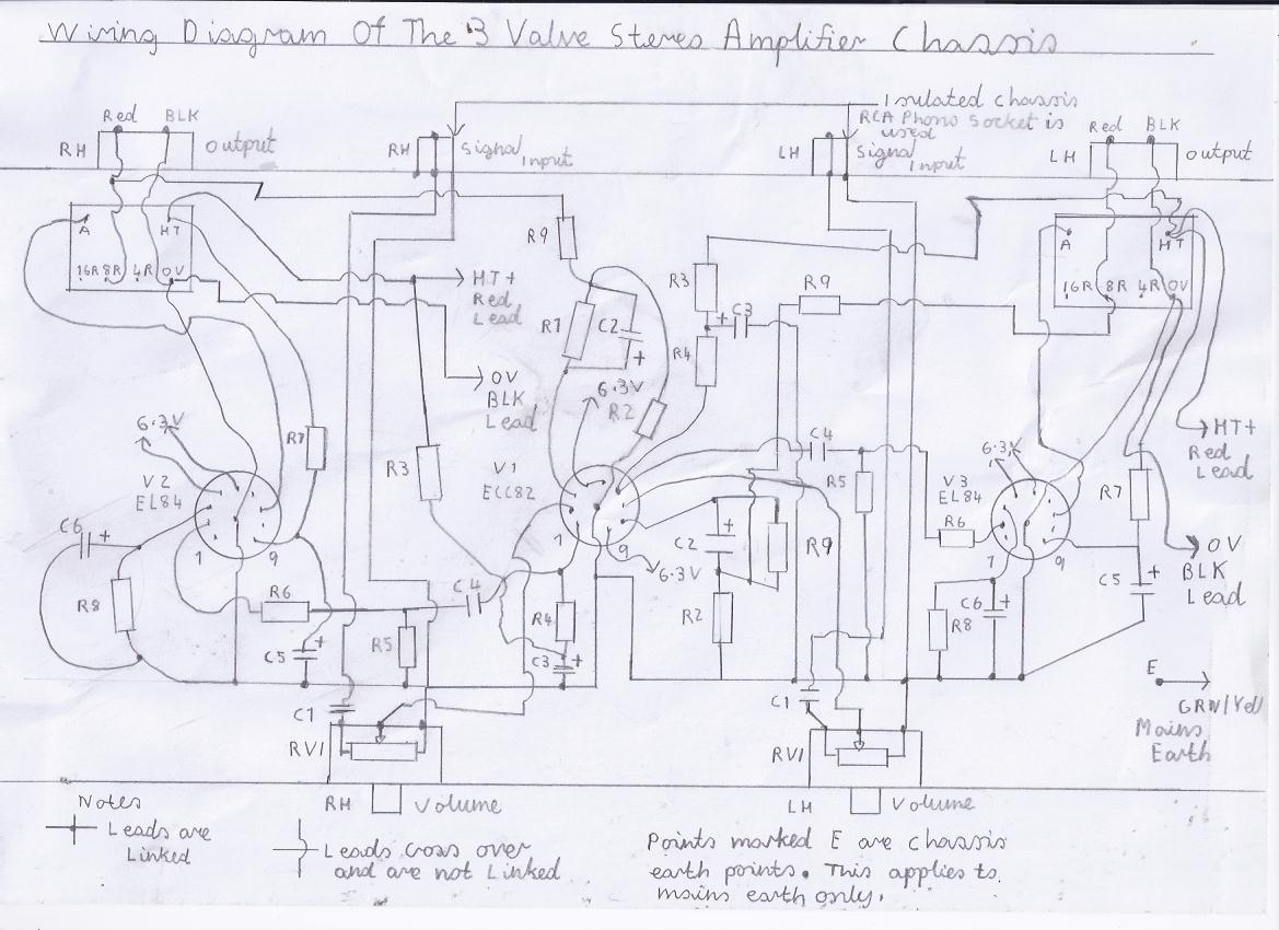
If everything has gone ok regarding the construction of the power supply you may now go ahead with the construction of both amplifier channels. You need to refer to picture 2 the circuit diagram and picture 8 for the wiring diagram. Before proceeding with the wiring up I will note the following important points regarding the earth and signal circuits. If you have noticed in all of my valve radio circuits all of the signal and 0V lines are connected directly to the nearest earth point on the chassis which is marked E. This is very important in radio circuits especially the VHF/FM circuits as the front end relies on a solid ground plain. In most valve Hi Fi amplifiers apart from the cheap record player amplifiers of the 1950s era, The 0V negative line is usually floating at a slightly higher resistance in relation to the mains earth and the chassis for the following reason. Because eddy signal currents are transmitted in a form of feedback through the mains earth it can introduce a hum loop when ancillary equipment such as phono preamplifiers are connected which can be very annoying to the most critical music listener who likes his amplifier to have no trace of hum in the background on quite or intermittent passages of music. For this reason the 100R Resistor R1 in the power supply takes care of this and you must also make sure you use the recommended phono input socket listed in the component list which has a nylon isolating washer specially designed for this purpose. The safety precautions remain the same as for the power supply circuit so less will be mentioned apart that you must check your work periodically making sure the cathode bypass electrolytic capacitors est. are connected in the correct polarity as shown in the circuit and wiring diagram. Also neat and tidy soldering is the successful key and try to make sure the wiring is not to crammed that can lead to short circuits. In particular the R8 cathode bypass resistor gets rather warm so try not to have leads or heat sensitive components running in too close proximity to this component. One final issue regarding the signal coupling capacitor C4. It must be of the high quality polypropylene type capable of withstanding 600V minimum or preferably 1000V for the following reason. Any slight leakage of even 1 volt can damage your output valves due to a higher then normal grid bias so for this reason do not attempt to use electrolytic capacitors as an alternative cost cutting exercise even if they are of the high voltage type as over a period of time they can become leaky or fail. Solid tinned copper wire is used for the earth bus and they must be separate for both channels apart from the spigot of the V2 ECC82 preamp tube has to share both earths. Also as it is a stereo design separate 0V returns are essential and solid black connecting wire is used. Red wire is also used for the HT 250V line which must also be a separate cable run. This practice insures that cross talk between both channels is kept to a minimum which can be generated by eddy feedback currents due to sharing the same 0V Line in a single return lead and another reason for why the chassis is isolated at a high resistance in respect to the 0V line. It is best to wire and test the left hand channel amplifier first and then proceed with the right hand channel amplifier after as this routine keeps mistakes to a minimum and will make fault finding easier. Before proceeding it is best to have all your components organised as working in a clutter is the worse cause of making mistakes such as losing components on the floor and other distractions that can be dangerous when working with high voltages. Also allow yourself plenty of time checking your work periodically for potential mistakes and if you feel tired or distracted leave it until another time. We will next go through the initial testing routine of your stereo amplifier which should be the moment of truth.
Initial Testing And Setting Up
We are now going to test the left hand channel amplifier before wiring and testing of the left hand channel can commence. Before starting this procedure please take note of this following and final reminder regarding safety. Just because you have got the power supply working ok does not mean to say that the amplifier will kick straight into action unless you have wired everything correctly and you have checked everything carefully such as the correct polarity of all the electrolytic capacitors within the entire amplifier circuit. Also check the resistor values very carefully and that you have no solder whiskers that can cause short circuits between the valve holder pins or other components. Whatever slight mistake is made, Damage will be limited provided that the HT Fuse is of the correct value. Also everything will be live again at both mains and HT potential so you need to be very careful not to touch any live parts. You must also make sure all speaker connections are securely connected before any power is applied as the amplifier output must see a continues 8 Ohm load as mentioned earlier. Also when the amplifier is part of an audio installation you must make sure none the speaker connections can not accidently come adrift in which it pays on a regular basis to check these connections particularly after a living room has been rearranged prier to house hold tasks such cleaning and dusting.
1. Observing the correct polarity connect an 8 Ohm speaker to the speaker output terminals. Make sure this speaker has minimum rating of 5 watts but as you are only doing a test, 2 or 3 watt handling is ok providing you do not crank the volume too high for long periods. Also incorrect polarity will not damage the speaker but as you will be driving the cone inwards rather then outwards, Music will sound more in the background particularly noticeable more after long periods of listening. Also the standard speaker cable is ok but for a permanent audio set up with cable runs likely to be longer then 2 metres I would go for the higher quality copper stranded cable that is used in higher powered amplifiers as this ensures maximum sound quality.
2. Insert the V1 ECC82 preamp triode into its respective holder and the V3 EL84 output valve.
3. Like when you tested the power supply circuits, The same precautions apply and you need to arrange some sort of wooden or concrete bricks to support the chassis as the under chassis needs to be facing upwards for its first testing routine and the valves must be clear of the worktop. Also make sure the unit is secure and can not fall.
4. Advance the LH Channel volume control RV1 fully clockwise to maximum.
5. Switch on the power and allow the valves to warm up. If all is well you should within 1 minute hear some soft blow noise in the speaker accompanied with a low pitched hum. If you hear high pitched oscillation then the feed back connection on the output transformer needs to be reversed in the opposite phase.
6. At this stage the valves should have a red glow and it is normal for the output valve cathode to have a blue glow.
6. If you see or smell smoke coming from under the chassis or hear a loud drowning hum you must switch off immediately and recheck your work.
7. Also if the valve anodes glow a cherry red or you see flashing between the elements, You have a high voltage short somewhere and it must be invested before carrying on any further.
8. Try touching the inner tip of the input phono socket. You should now hear a loud pitched buzz which means everything is working ok and an input source such as a CD player, Crystal or ceramic phono pickup can be connected. NB Moving coil or magnetic pickups need a separate phono pre amplifier stage and I hope in the near future to include one as a constructional article.
9. On mid to high volume levels, The music depending on the recording quality should be able to be heard in crisp clear reproduction with no distortion.
10. If all at this stage has gone well, You can now go ahead constructing the right hand channel amplifier. The instructions are the same as the LH Channel so no more information will be mentioned other then you must always remember the usual safety precautions.
11. Before all bottom chassis covers are fitted prier to completion check that you have given any bare component lead plenty of clearance of at least 5mm minimum. To avoid microphonics make sure the signal coupling capacitor surfaces do not touch the bottom casing.
12. This now completes this amplifier project and there will be a simple hints and tips section to close this article.
Simple Hints And Tips Regarding The Use Of Your Amplifier
1. When the amplifier is not in use for long periods always switch it off particularly when retiring for the evening or leaving your premises for any length of time.
2. Avoid intermittent spells of switching on and off your amplifier as this reduces valve life.
3. Using your amplifier more often then at least 2 times a week keeps the smoothing capacitors healthy and you may also see an increase in performance due to the burn in affect of the valves.
4. After switch on, Allow at least 10 minuits for the valves to reach maximum temperature as this does also see a considerable increase in performance and at this stage the output at high volume levels will sound less distorted as the valves will be at full working temperature to achieve full electron emission from there cathodes.
5. When cleaning dust from the chassis or valves do not use any kind of fluid or household polish as this can blacken the valve envelopes due to the heat action and reduce valve life. Do not use any aerosol sprays within the proximity of your amplifier as this could also shatter the valve envelopes causing expensive damage. A soft non abrasive cloth is ideal for cleaning dust off your amplifier chassis and you must make sure the valves are cool before proceeding.
6. For the best stereo affect make sure your speakers are at least 6 feet minimum apart depending on room size and allow at least 100mm clearance from the walls for best sound quality.
7. Although you need your amplifier to be reliable it pays to check things over at least every 6 month for signs of stress or overheating. Under normal use, The output valves should have a useful life of 10000 hours which is about 5 years. It is advisable to have some spare valves handy so you are not caught out when it is that special occasion such as a party or other event.
Finally
I wish you all the success in building this wonderful amplifier project and hope you have many happy years of listening. Remember vinyl is still very alive and I hope to introduce a suitable valve phono preamplifier for this project with input selection and tone control.
Links To My Other Related HI FI Projects
Simple Stereo Preamplifier Circuits For The 3 Valve Stereo Amplifier
Transistor Pulse Counting FM Receiver
Double Conversion Pulse Counting FM Superhet Receiver With 10.7 MHZ First IF Stage
Single Conversion 6 Transistor 10.7 MHZ Pulse Counting Receiver, Designed For Stereo FM Reception
6 Valve VHF/FM Pulse Counting FM Tuner Using Safe 25Volt DC HT Line
Valve Version Of The 10.7 MHZ Double Conversion VHF/FM Pulse Counting Tuner
Solid State AM/FM Pulse Counting Receiver
Site Map Of All My Webpages And Favourite Valve Radio Related Links