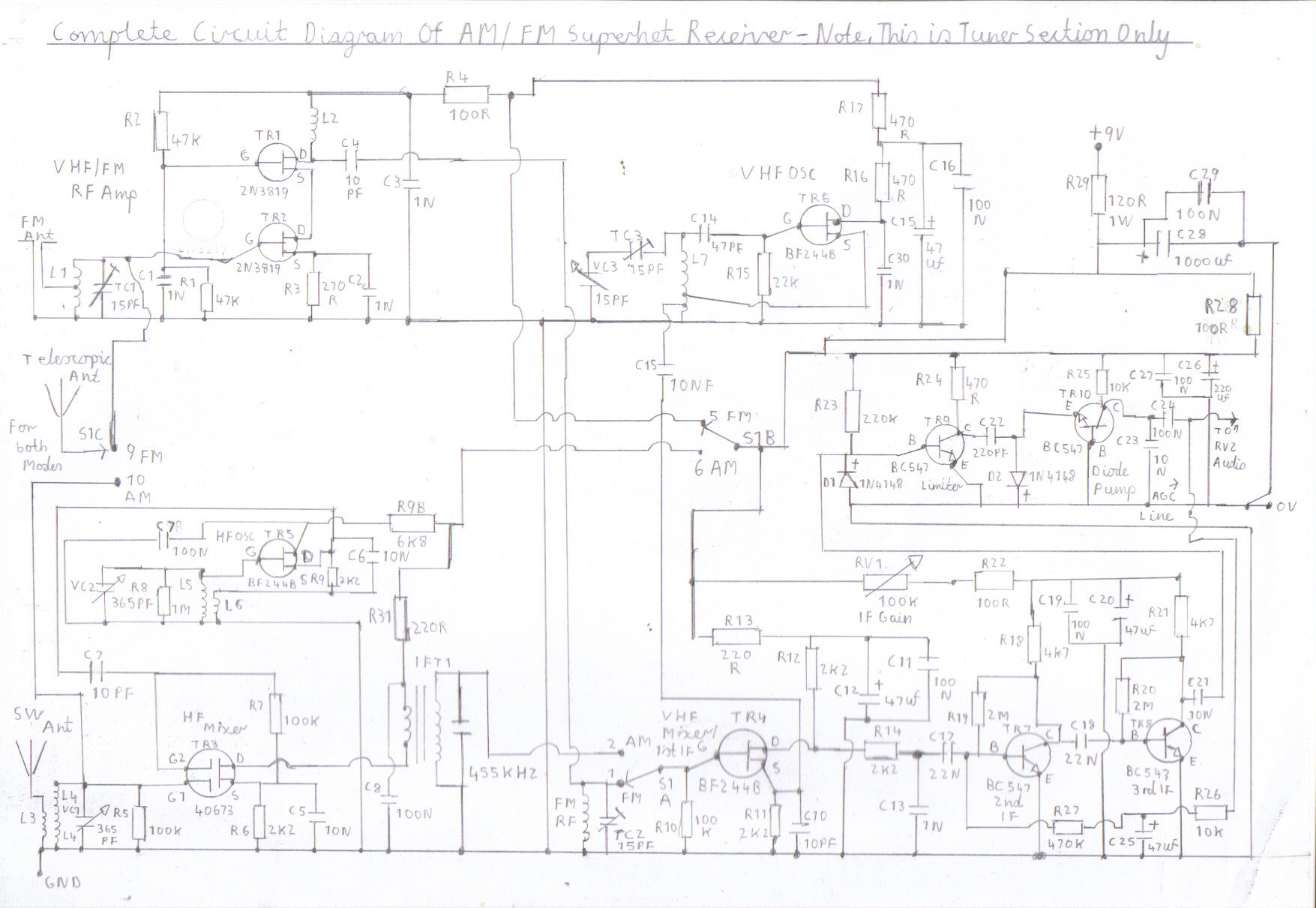
Solid State AM/FM Pulse Counting Receiver
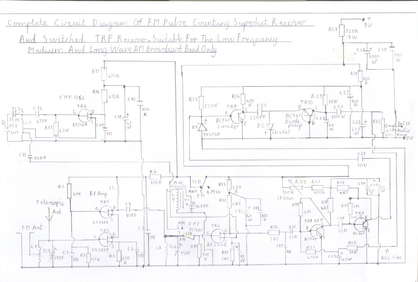
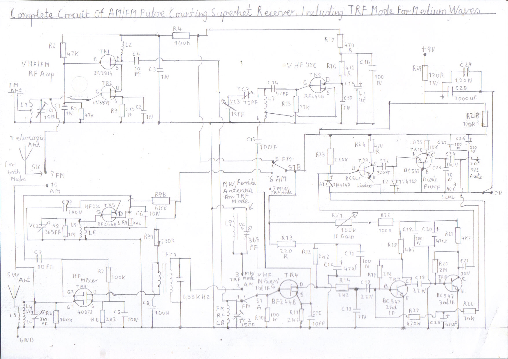
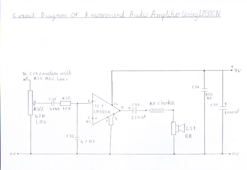
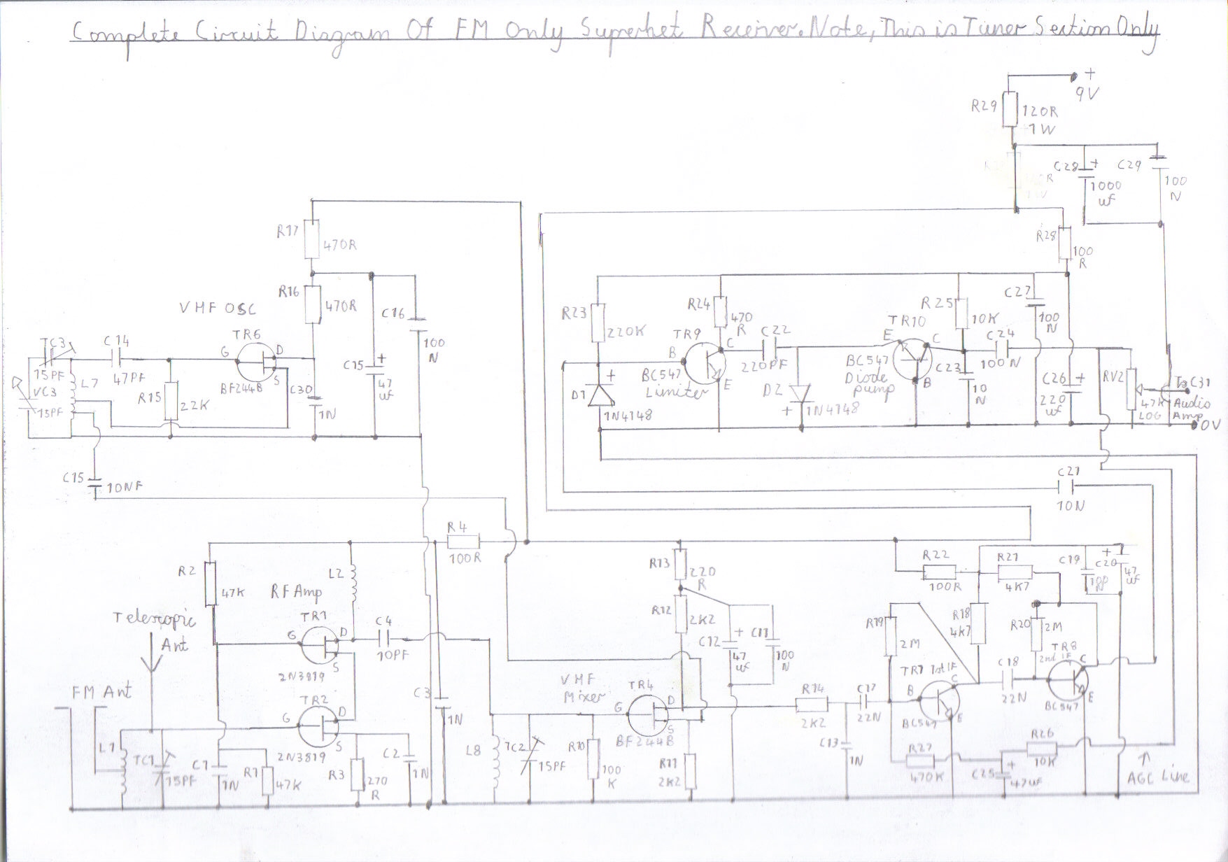
This part of my site features an updated version of my present Transistor FM Pulse Counting FM Receiver . The circuitry is very similar but has had slight modifications. It now uses grounded tuning using a Hartley electron coupled oscillator and also AGC Automatic gain control. It also features AM Medium Wave broadcast band reception by using the VHF mixer as part of the RF amplifier for a low frequency TRF receiver using a ferrite rod antenna and separate tuning capacitor when FM is not used. It is also Shortwave compatible but uses a 455KHZ IF transformer to replace the ferrite rod antenna and a separate mixer and oscillator is used which makes this receiver an AM superhet receiver as well as an FM design. As there are four different configurations of this receiver I will describe the FM only version first. The 1st stage is a cascode VHF RF Amplifier consisting of 2 2N3819 FET transistors TR1/ TR2 and as well as providing good sensitivity it helps prevent radiation of the local VHF oscillator. The 2nd stage TR4 is the VHF mixer and uses a BF244B FET and as this circuit is a bit simpler to the dualgate MOSFET type used in the previous FM receiver it still gives excellent performance and low noise. The oscillator signal is injected into the source and the bypass capacitor C10 has been chosen very carefully regarding its low value. The value is just high enough to bypass R11 to ground without shorting the oscillator signal to ground which would spoil the performance of this set so this capacitor value is very critical. The 3rd stage TR6 is the local oscillator and this also uses a BF244B FET and source feedback is used similar to cathode feedback used in my valve version of this receiver 6 Valve VHF/FM Pulse Counting FM Tuner Using Safe 25Volt DC HT Line . As a result of using this type of oscillator the tuning capacitor VC3 can be grounded at earth potential in a metal case resulting in less hand capacitance effects and the TC2 trimmer for the L8 RF coil in the VHF mixer can also be combined. The purpose of these 2 stages is as follows. As with any superhet receiver the mixer is always tuned to the reception frequency. For example. Supposing you want to tune into your local station BBC Tees on 95.0 MHZ. In the case of this receiver using a low IF of around 150KHZ you would need to be tuning the local oscillator to 95.15 MHZ which is above the reception frequency, so this makes up the combined sum which we call frequency conversion. The 4th and 5th stages which is the 2 BC547 silicon transistors TR7 and TR8 form the intermediate frequency IF amplifier. Its purpose is to amplify the converted 150KHZ IF signal to a suitable level to drive the limiter and demodulator. The resistance capacitor network R13 and C13 form an IF filter to reject the VHF megacycle frequencies and allow the converted 150KHZ IF signal to pass through ready for amplification. The coupling capacitors C17 and C18 set the frequency response at 150KHZ and as a result that is why we can have a decent sounding FM receiver with no 10.7 MHZ IF coils to wind. The 6th stage which is the TR9 BC547 silicon transistor and the D1 silicon diode form the Limiter circuit and its role is to shape the FM signal into a clipped waveform before demodulation to remove any AM components. The 7th and final stage which is the TR10 BC547 and the D2 silicon diode form the voltage doubling diode pump detector. TR10 is used in common base mode along with D2. As well as C22 being a coupling capacitor it also forms as part of the voltage doubling action which sets the pulse amplitude rate at just a suitable level to switch D2 and TR10 on and off. It is this rise and fall rate that forms the demodulation of FM signals. AGC bias is taken from the volume control RV2 of the audio amplifier and the signal is feeded back into the base of the 1st IF amplifier TR7 to form the AGC loop. The resistor R26 along with C25 decouple audio from being fed back into the IF stages and also provide smoothing. The stronger the RF signal is fed back into the base of TR7 1st IF stage the more the collector current is reduced resulting in lower gain and stronger stations are received at the same volume level without the need to readjust the audio volume frequently. Although the limiting action on a FM receiver takes care of AGC, the reason why it has been included in this design is because the other three configurations feature Shortwave and the AM/MW broadcast bands where reduced gain and selectivity is important. Please refer to picture 2 for the circuit diagram regarding the FM only version of this receiver. The second version of this receiver uses the same circuitry for VHF/FM reception but is also capable of AM/MW reception by replacing a ferrite rod antenna and separate tuning capacitor for the VHF RF coil L8. Shortwave reception up to about 75 metres 4.00 MHZ is also possible by winding suitable coils but the performance will start to drop considerably above these frequencies when using TRF mode. I will describe how this works and what needs to be modified to enable this configuration. The diode charge pump circuit stage 7 will function as an AM voltage doubler detector and is very capable of very good audio quality. In fact so good you may end up binning your old MW trannie. The first essential modification concerning the IF amplifier needs to be carried out as follows. The additional component needed is RV1 which is an IF gain control wired in series with the decoupling resistor R22 to reduce the gain of the IF amplifier and although this is not essential with FM reception, omitting this component will limit the AM signal causing excessive signal distortion and unintelligent demodulation of the signal. When receiving FM this control can be simply readjusted to allow full IF gain. The modification concerning the RF circuitry is a bit more complex but I will describe as follows. Many new constructors to VHF receivers who have had very good success with building short wave receivers of all kinds are easily led to believe that by adding simple band switching in the mixer and oscillator circuits that a simple multiband all mode receiver can be produced but unfortunately things do not work out that way with VHF for the following reason. Long leads particularly in the RF oscillator circuits of a VHF receiver can lead to instability and backlash which means unstable tuning and in some cases the receiver not working at all. This happens because every centimetre of wire counts as a critical inductance at these frequencies compared to the low frequency shortwave bands. However. Looking on the bright side of things the VHF mixer circuit is not as critical to switch and in this design I will describe how this is achieved. A 4 way 3 pole rotary switch is used to simply disable the positive supply to the VHF RF oscillator and RF amplifier circuits. A second pole on the switch then switches the VHF mixer from the FM RF coil to the medium wave ferrite rod antenna and tuning capacitor which then forms a simple MW TRF receiver. When using the receiver in this mode the VHF mixer and both IF amplifiers function as a wideband RF amplifier and as a result of this it is possible to get near Hi Fi quality AM. In fact any one lucky enough to be building receiver projects in the 1970s will remember the ZN414 IC receiver package which also works in the same way as this configuration. Please refer to picture 3 for the circuit diagram of this receiver configuration. The third version of this receiver is a combined FM and Short Wave Superhet receiver configuration which I will describe as follows. The configuration is basically the same as the MW TRF configuration but a 455KHZ IF transformer replaces the MW ferrite rod antenna and a separate mixer and oscillator is used. The positive supply is also switched from the VHF oscillator and RF amplifier to what we call the HF mixer and oscillator needed for AM shortwave reception. The HF mixer TR3 is very much the same circuit used in my other Transistor Pulse Counting FM Receiver and uses my beloved 40673 Dualgate MOSFET which performs excellent on the HF short wave bands and is very stable. The HF local oscillator TR5 uses a BF244B in source feedback mode and grounded tuning is also used. The rotary switch S1 also uses a third pole to switch the telescopic antenna from L1 on the FM RF amplifier to L4 on the shortwave HF mixer. I regret to say that the availability of shortwave RF coils is very scarce as they are no longer produced for the home constructor straight off the shelf like they once was. For that reason it is best to build the TRF AM version first. Also if you want to try your hands at winding them yourself then this page may help you out Introducing Superhet Receivers' Featuring Add On Converter For The Two Valve TRF Receiver as the coils for that design are wound in the same configuration. Please refer to picture 4 for the circuit diagram of this configuration. The 4th configuration of this receiver is very much the same as the 3rd but the switching of S1 functions for all three modes which may be an advantage if winding your own coils as medium wave oscillator coils are very hard to wind and this is due to the fact that the tracking with the mixer must be very precise compared to the high frequency short wave bands or the performance will be very poor. Please refer to picture 5 for the circuit diagram. The audio amplifier is a very simple affair and uses the LM380N which has been popular since the early 1970s in cheap record players and music centres of that era. It also gives excellent audio quality with this receiver and features short circuit protection and thermal shutdown. I will describe the circuit as follows. RV2 is the volume control and also forms bias for the AGC line. The resistance capacitor network C31 C32 and R30 form an RF filter to stop RF currents from entering the signal input as this can be well known to course parasitic oscillations that can ruin the performance of this receiver. C33 is also necessary, so the passage of AC voltage only appears on the speaker output and I will briefly mention the purpose of the RF Choke. When using a short antenna on VHF it has been well known on my previous designs for constructors like myself to experience violent oscillation when using the receivers at mid to high volume levels. This is because one of the speaker leads are connected to the 0V negative return line and as a result this lead acts a VHF antenna. It is more of a problem when using short speaker leads and an RF choke has greatly eliminated this problem. This particular component consists of about 50 or more turns of say 26 SWG enamelled copper wire wound onto a ferrite bead does the trick wonderful. A separate 9 volt battery independent of the receiver is also recommended for this audio amplifier for similar reasons. Please refer to picture 6 for the circuit diagram of the audio amplifier.
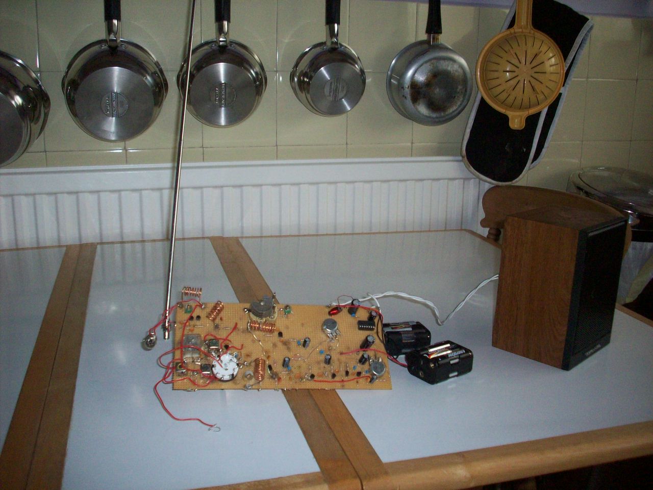
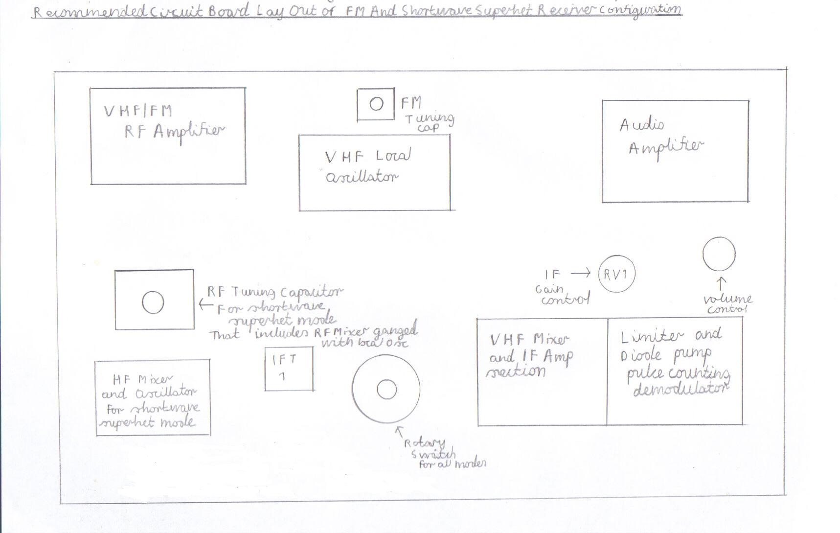
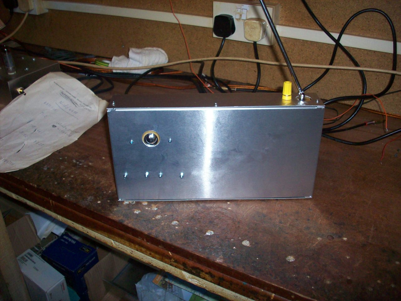
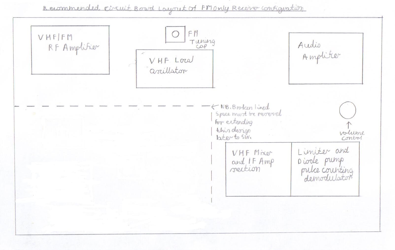
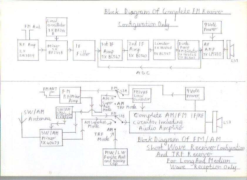
Block diagram of the complete FM receiver configuration and pictured above is a complete switched AM/FM configuration with Superhet mode for Shortwave/AM reception. A separate switching facility for Medium Wave TRF mode is also included using a ferrite rod aerial. Please refer to pictures and instructions below for construction details. Also click on the following link YouTube - My Home Constructed Portable Solid State SW And FM Superhet Receiver.MP4 to see my own version of this design working.
|
|
|
|
|
|
|
|
|
|
|
|
|
|
|
|
|
|
|
|
|
|
|
|
|
Please left click on selected picture to enlarge image.
Special Precautions And Guidelines When Constructing this Receiver
Firstly this receiver uses a 9 volt power supply and as a result there is not any electric shock hazard like there is when building valve receivers that require a 100 to 250V HT line. However. There are just four simple precautions you must take note of and then you should have an enjoyable time building and setting up this receiver. Dry batteries that used to be available in the Eveready range of HP7 or the U2 category are sadly no longer made. As a result of this we all have to resort to the Duracell alkaline equivalents that have the advantage of longer life but deliver a more heavier current that is to dangerous for young children to experiment with for the following reasons. They do not like continues short circuits as they can warm up very quickly and even explode creating a fire hazard as well. Also don't try the silly old tricks we all used to do with the drycell PP3 types such as testing them for a tingling sensation by placing them on your tongue or warming them in the oven to prolong life. You must take very great care with the battery polarity as well, as the transistors particularly the FET Field effect transistors used in this design are very easily damaged and on a closing note the field effect transistors are static sensitive so you must handle them with great care using plastic tweezers if at all possible when inserting into the circuit board. It is also a good idea to leave these until last job as you come to wire each stage individually and try not to allow more then 5 seconds of heat time when soldering these components onto the circuit board. You must also take care with the polarity of the electrolytic capacitors used in this receiver for the following reason. Anyone reading this page may remember the dreaded fear of switching on an old valve radio that has been stored for 20 years or more in your Grand Dads attic, hopping to be welcomed with music of some sort or worst of all a loud frightening bang accompanied with smoke. Similar things can happen in low voltage transistor sets believe it or not and despite the voltage being only 9 Volts, it is these modern alkaline batteries that cause this danger because as mentioned previously they deliver much heavier currents then dry batteries. As a final note, double check your work very carefully before you attempt to apply power checking for possible mistakes such as solder bridges and incorrect polarity of diodes and transistors then on a brighter note of things, everything should then go to plan.
Construction Of The LM380N Audio Amplifier For All Versions Of This Receiver
|
|
|||
Please left click on selected picture to enlarge image.
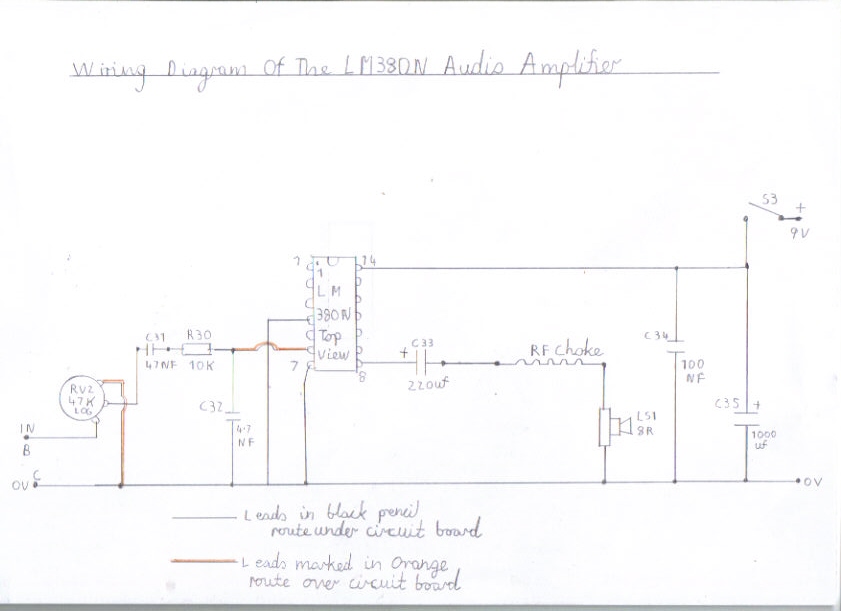
1. Please refer to pictures 1 and 2 above for the circuit and wiring diagram of the audio amplifier. You will also need to refer to the components list by clicking the following link Components List Of AM/FM Pulse Counting Receiver . All stages of this receiver design are broken down into modules with each terminal connection point in alphabetic sequence to make understanding of the connections of each stage easy and minimizes mistakes. Also veroboard pins must be used for interconnecting leads to each point in all circuits as it makes modifications and fault finding easier.
2. For all versions of this receiver the audio amplifier must be constructed in the top right hand corner of the circuit board and the plain Veroboard available from Maplin Electronics is recommended for all designs, order code JP51F, size 300 X 100 mm.
3. Start by carefully following the wiring diagram and make sure that that IC1 is mounted in the correct orientation as shown. A 14 pin socket is also recommended for mounting this IC, rather then soldering direct to the board as it is very heat sensitive. The speaker RF choke is wound on a ferrite bead and consists of around 25 to 50 turns of 26 SWG enamelled copper wire bonded with a little adhesive such as evostick or superglue to support there leads should surface. This choke helps to prevent VHF RF currents from circulating through the speaker output that tends to result in RF instability such as oscillation and other unwanted feedback particularly when using the short telescopic antenna.
4. As I said earlier in the introduction text, you must observe the polarity of certain components such as electrolytic capacitors, Diodes and transistors. Also, double check your wiring very carefully before applying power to any part of the circuits as this may result in expensive damage. This also applies to each stage including the rotary switch wiring in all the AM/FM versions of this receiver. Leads marked in red pencil are link wires that route over the circuit board and leads marked in black solid pencil route underneath the circuit board on all modules of this design.
5. If you have proceeded carefully with all the above stages you may now prepare to test this stage.
6. Connect an 8 Ohm speaker of not less then say 1 Watt rating for this amplifier because it is capable of about 2 Watts output when using a 18V power supply and over 500 milliwatts when using a 9 Volt supply.
7. Because it is the first time you are applying power to this stage, it is advisable to use a 9V bench power supply incorporated with a current limiter or dry batteries if available.
8. Making sure you observe the correct polarity, connect a 9 volt power source.
9. If all is well you should now hear a soft hiss in the speaker. Rotate RV2 fully clockwise and touch terminal B which is the audio input. You should now hear a high pitched hum which means this stage is working properly.
10. If all the above procedures have gone to plan you may now continue with building the receiver configuration of your own choice.
Construction Of The FM Only Version Of This Receiver
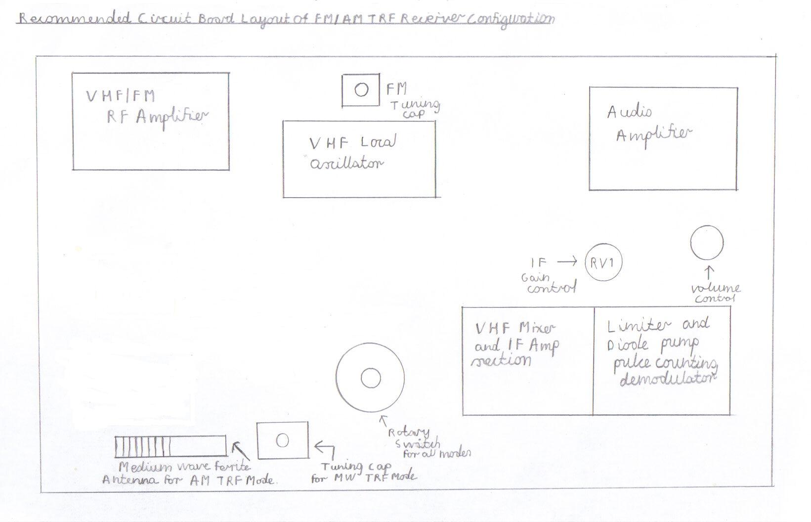
Please refer to picture 3 for the recommended layout diagram and picture 4 for the circuit diagram listed below. You also need to refer to Components List Of AM/FM Pulse Counting Receiver
|
|
|||
Please left click on selected picture to enlarge image.
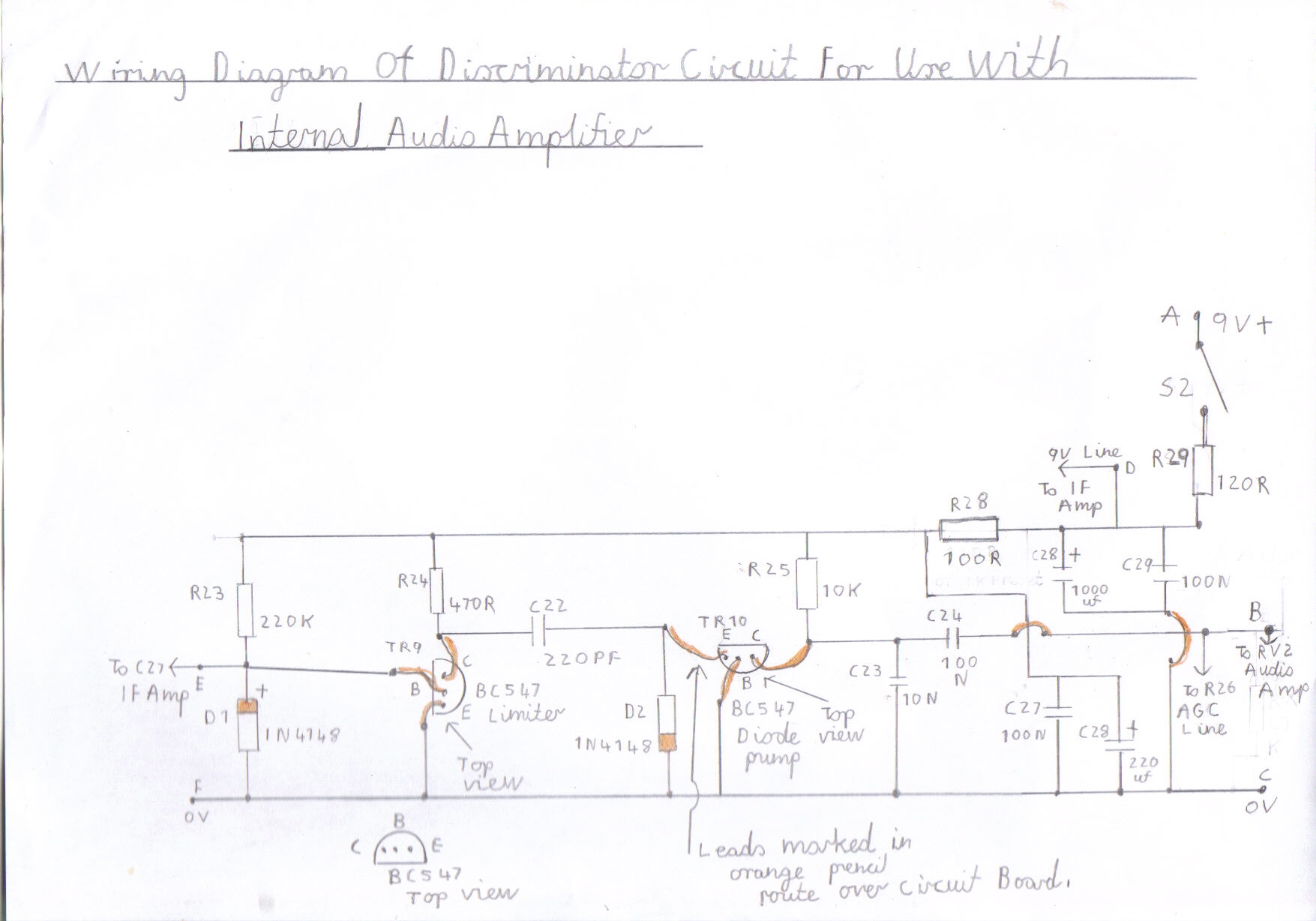
As you can see in the layout diagram of picture 3 the broken boundary lines of unoccupied space in the bottom left hand corner must be reserved for in case you intend extending this configuration to the AM/TRF or Shortwave superhet version later on. Picture 4 is also the circuit diagram for this configuration. If you are now familiar with these 2 diagrams it is now time to start constructing the second stage which follows the audio amplifier, that is the discriminator circuit. As there are two configurations of this circuit please refer to pictures 5 and 6 listed below.
|
|
|||
Please left click on selected picture to enlarge image.
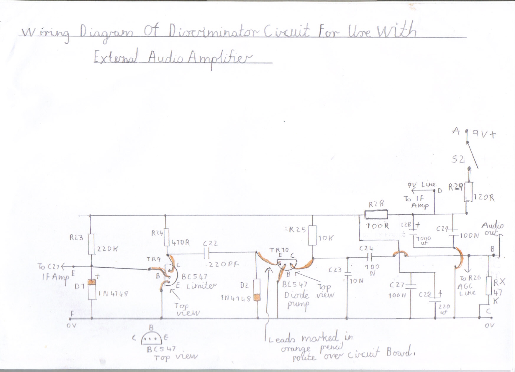
1. You need to refer to picture 5 if you intend using the receiver with the internal LM380N power amplifier as AGC bias is provided by the RV2 Volume control. If you intend to use the receiver as a tuner with an external audio amplifier you need to refer to picture 6 which is basically the same circuit except a 47K 1/4 watt resistor replaces the RV2 volume control for AGC bias. You will also need a 10NF coupling capacitor wired between point B of the discriminator and the external audio amplifier. This capacitor must be rated at least about 400V DC if you intend connecting the tuner to a valve amplifier for safety reasons regarding high voltages and don't even think of connecting to an AC/DC type that incorporates a live chassis or an electric shock hazard may exist, particularly if the chassis is wired at live potential in the mains lead rather then neutral.
2. If you are now familiar with everything regarding this stage, you may now start wiring it up and as previously mentioned, you must take care with the polarity of certain components such as the electrolytic capacitors. The red stripe of D1/D2 must correspond exactly as shown in the wiring diagram and the BC547C transistors are top views identified in a half moon shape and these must also correspond exactly as shown in the wiring diagram.
3. If you are confident you have followed all the above procedures correctly you may now test this stage.
4. Connect the output of the discriminator, that is point B to the audio amplifier at point B of the amplifier input.
5. Connect the point C 0V line of the discriminator to the point C 0V line of the audio amplifier.
5. For stability reasons you need a separate 9 Volt battery supply independent of the audio amplifier and this applies to all circuits in the receiver.
6. Connect about 2 metres of insulated wire to point E of the discriminator circuit to act as a temporary antenna.
7. Reconnect the audio amplifier and advance the RV2 volume control fully clockwise.
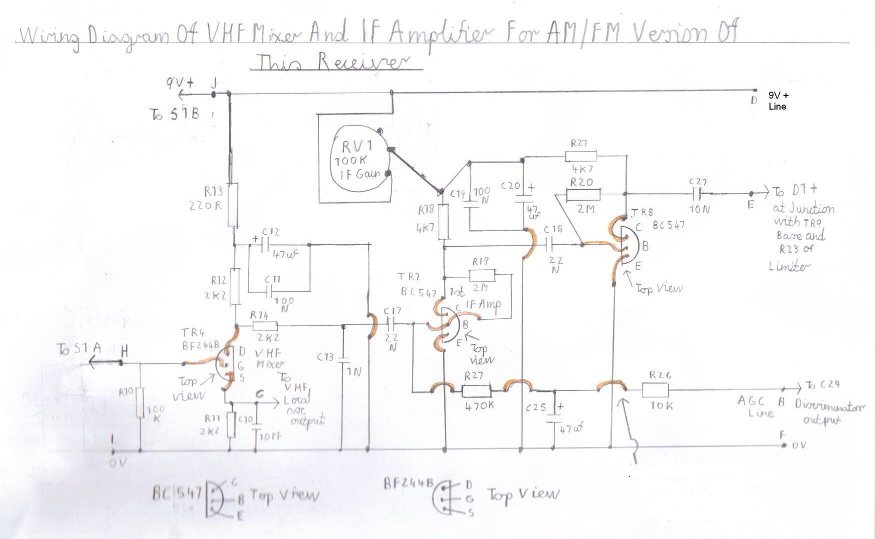
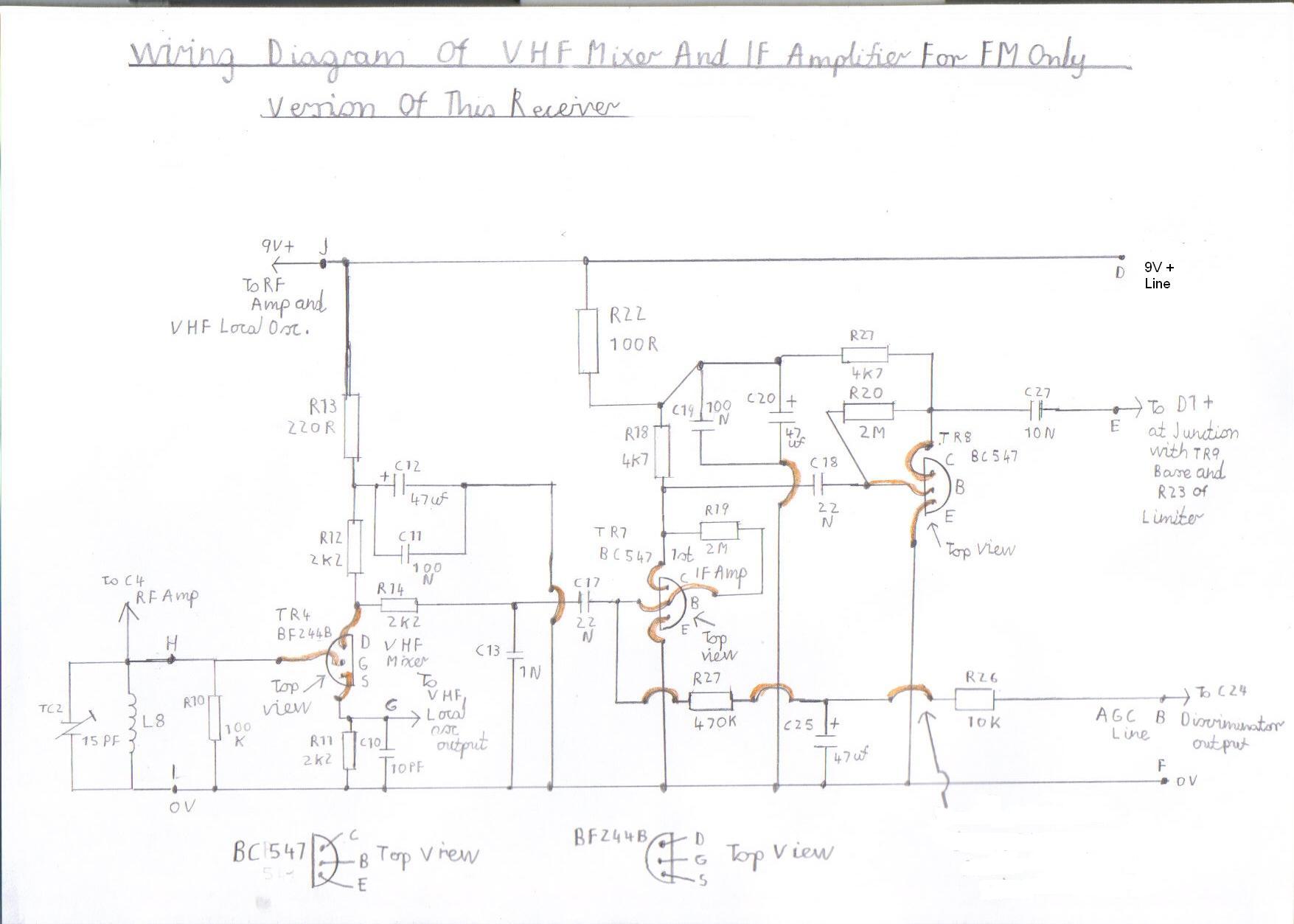
8. Connect the discriminator circuit to the separate 9 volt supply with the positive 9V+ line connected to point D and the negative 0V line to point C. If all is ok you should hear a bit of RF activity such as stations in the medium wave and long wave bands cluttered together with no separation. This stage is simply acting as a untuned detector stage and if this sounds the case, everything regarding this stage is working ok and it is now time to refer to the pictures 7 and 8 listed below for constructing the IF amplifier and VHF mixer circuits. A brief word of explanation regarding the IF amplifier and VHF mixer circuit of picture 8. It is basically the same circuitry as in picture 7 for the FM only version except it has an IF gain control that is essential if you are intending to extend this receiver configuration to the FM/MW TRF Receiver or short wave superhet version. The information in the circuit diagram of picture 8 only relates to the rotary switch wiring for all the AM/FM configurations. NB All errors in the wiring diagram of picture 5 and 6 regarding the discriminator circuit have now been corrected and you can now confidently follow these diagrams. Sorry for the inconvenience and hope you get things working ok.
|
|
|||
Please left click on selected picture to enlarge image.
9. If you are now familiar with the wiring diagram of pictures 7 and 8 you can now go ahead with constructing this stage. It is basically constructed in the same way as the discriminator circuit, taking the usual precaution regarding the correct polarity of components such as the transistors and electrolytic capacitors. Do not at this stage attempt to Connect the VHF RF coil or the TC2 trimmer until this circuit has been tested.
10. If you are now sure you have followed this stage correctly regarding the wiring of the VHF mixer and IF amplifier it can now be tested.
11. Connect the point D 9V + line from the VHF mixer / IF amplifier to the point D 9V + line of the discriminator circuit.
12. Connect the point E IF Amplifier output from C27 to the point E input of the discriminator at the junction with D1, TR9 Base and R23.
13. Connect the point B AGC loop from R26 of the IF amplifier to the point B input of the audio amplifier at RV2.
14. Connect the point F 0V line from the IF amplifier to the point F 0V line of the discriminator.
15. At this stage, if you are confidant everything is wired up correctly you can now reconnect the power to the AF Amplifier and all stages.
16. If all is well you should be able to hear a rushing sound which means everything sounds alive and is working at this point. Also if you have built the VHF mixer and IF amp featured in picture 8 for all AM/FM versions, You will have to advance the RV1 IF gain control to archive full gain for the discriminator to function properly when using VHF/FM mode.
17. Try touching point H of the VHF mixer and you should hear a muffled buzzing noise which also means everything is working correctly so far and you can now go ahead with winding the VHF RF coil L8 and wiring the tuned circuit.
18. The L8 VHF coil in this design is constructed using 15 Amp house lighting cable of 1.5 mm with its conductors stripped down. This coil is about 10 mm diameter self supporting and is aircored. You need a total of 9 turns altogether and a 1.5 volt AAA size penlite battery will assist at this stage. As you are dealing with very high frequencies at this stage, you must make sure the wiring from the VHF tuned circuit to the input of the VHF mixer at point H and the 0V line is kept as short as possible.
19. If you are thinking of extending this FM only configuration to the AM/FM versions later, you must only connect the VHF RF coil and tuned circuit to point H and point I 0V line on a temporary basis as this stage will need to be modified later for the wiring to the rotary switch.
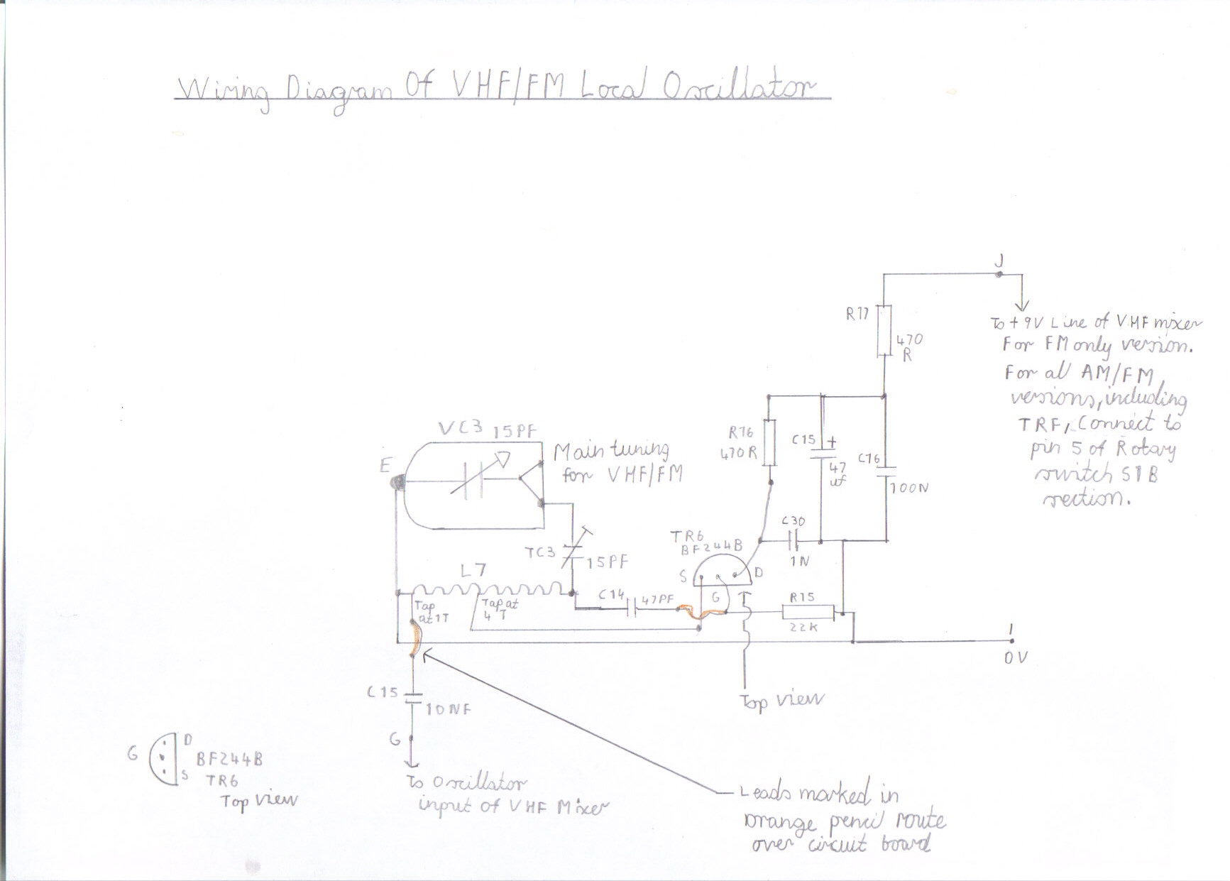
20. If everything seems ok at this stage please refer to picture 9 listed below for the wiring diagram, regarding construction of the VHF RF oscillator.
|
||||
Please left click on picture to enlarge image
21. If you are now familiar with the wiring diagram of picture 9 you may now go ahead with constructing this stage which needs more precaution regarding the wiring of the tuned circuits for obvious reasons. As when wiring all VHF circuits short wiring is the order of the day or poor performance or loss of frequency coverage will result, particularly at the high frequency end of the FM band. Other then that, this circuit is very simple and is a very stable oscillator. Like the VHF mixer, the L7 oscillator is the aircored self supporting type and consists of 9 turns of 15 amp 1.5 mm house lighting cable and is wound in the same way. The source or cathode tap must be around 4 turns from the earthy end as shown in the wiring diagram. Also one note regarding the source tap. Do not for any reason allow it to become open circuit when the power is applied to this stage as there will be no bias and the TR6 FET will be destroyed. The C15 oscillator injection capacitor must be also tapped around 1 turn from the earthy end of the coil and this may require a bit of experimentation with trail and error. Getting the oscillator injection from the drain of TR6 was tried originally but resulted in low sensitivity and as this later method is not my favourite it still works satisfactory. As a final reminder before connecting up this stage, do check the polarity of the transistors and electrolytic capacitors. If you are confident you have wired everything correctly regarding this stage it is now time to connect and test this stage which will be the big moment of truth.
22. Connect the point J 9V + line of the VHF local oscillator to the point J 9V + line of the VHF mixer.
23. Connect the Oscillator output at Point G to the Oscillator input of the VHF mixer at point G, that is at the junction of TR4 Source and R11/C10.
24. Finally connect the point I 0V line to the point I 0V line of the VHF mixer.
25. If you are confident you have followed these procedures correctly you may now carry out the setting up of the FM only design regarding the RF and oscillator circuits. Fortunately the alignment in this design does not need the complex test gear such as signal generators or oscilloscope like the 10.7 MHZ designs that incorporate a ratio detector but the signal generator may be a great help for aligning the Shortwave superhet version or if you want to use different VHF frequencies other then the FM band.
26. Connect a 1.5 Metre piece of wire to point H of the VHF mixer input or better still, an outdoor FM antenna
27. Reconnect the 9V power supply to all stages.
28. Try rocking the VC3 tuning capacitor and it may be possible to tune in a few stations. If this is so, try adjusting the TC2 RF trimmer for maximum signal strength with minimum distortion. Also if you have built the IF amplifier circuit for the AM/FM version of this receiver, make sure the RV1 IF gain control is set to maximum or FM will sound weak and distorted. If all these steps have gone OK it is now time to align the frequency coverage before going any further to construct the VHF RF amplifier circuit.
29. For example the UK station BBC Radio 2 broadcasts on the low frequency part of the FM band on about 89.3 MHZ from the Yorkshire Emily Moor Transmitter. If you find you are receiving this particular station with the VC3 tuning capacitor vanes half way open this needs correcting.
30. The TC3 oscillator trimmer can correct this which I will briefly describe. When the vanes of TC3 are fully open the capacitance of VC3 is electrically lowered. The opposite is true when the vanes of TC3 closed, the capacitance of VC3 is higher. So in the case of you receiving Radio 2 with the tuning capacitor half way meshed, you need to slowly open the vanes of TC3 and at the same time, slowly close the vanes of VC3 until you can receive Radio 2 at the lower end of the band without any dead ends, that is extended low frequency coverage before 87.5 MHZ.
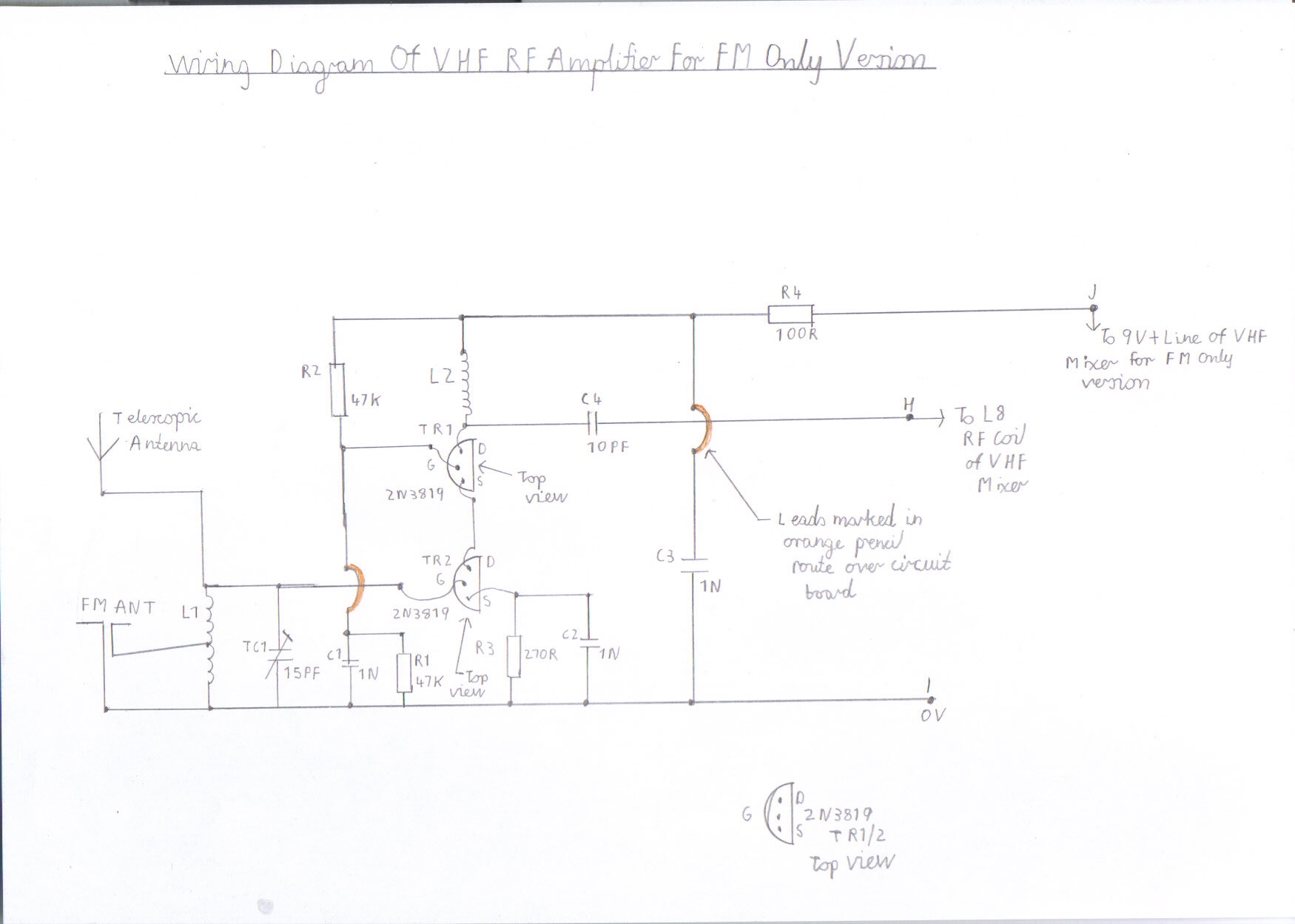
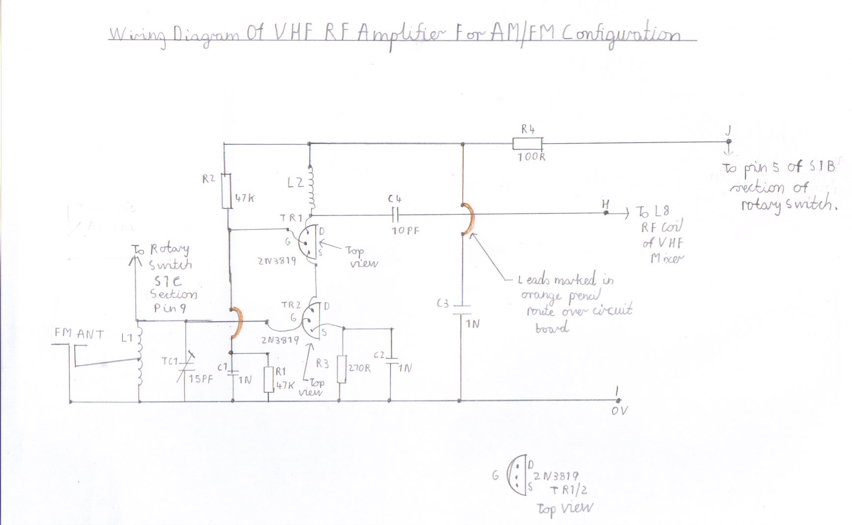
31. If the above procedure has gone OK, try tuning stations at the middle of the FM band around 95 MHZ. Readjust the TC2 RF trimmer for maximum signal strength. This should now set the frequency coverage almost spot on and by tuning further up the band around 104 MHz you should be able to pick up Classic FM and a few other ILR stations such as Galaxy and Minster FM. This now completes the setting up of the VHF circuits. However, This receiver is capable of better performance regarding sensitivity then at its present state and to achieve this you need to refer to pictures 10 and 11 which is the VHF RF amplifier circuit. Before proceeding with this circuit I will briefly explain the information regarding the VHF RF amplifier of picture 11. It is exactly the same circuitry as the one for the FM only version in picture 10 except the wiring information relating to the connections is configured for the rotary switch on all three AM/FM versions. If you are thinking of constructing the FM/MW TRF version, simply ignore the wiring of the telescopic antenna to S1C and connect the telescopic antenna as shown in the FM only configuration of picture 10.
|
|
|||
please left click on selected picture to enlarge image.
32. If you are now familiar with the wiring diagrams of pictures 10 and 11 you can now go ahead with the VHF RF amplifier. It is constructed in the same manner as the VHF mixer circuit and as a final reminder, make sure you keep all wiring to the tuned circuits as short as possible and observe the correct polarity of the field effect transistors TR1 / TR2. The RF coils are constructed in the same way as the VHF mixer with the same gauge wire, except 7 turns is used for L1 and is centre tapped when using an external FM antenna. L2 is also 7 turns of the same gauge and as it is untuned, it acts as an RF choke to give a wide bandwidth to help prevent self oscillation due to the high gain of this circuit. If you are confident you have wired this stage correctly you can now go ahead with the final testing and setting up of the FM only configuration of this receiver.
33. Connect the point J 9V + positive line from the VHF RF amplifier to point J of the VHF mixer.
34. Connect the Point H RF output from the VHF RF amplifier to point H of the VHF mixer input.
35. Connect the Point I 0V line from the VHF RF amplifier to the point I 0V line of the VHF mixer.
36. Connect a short 1 metre length of insulated wire or telescopic antenna to L1 of the RF amplifier at the junction of TR2 Gate and the TC1 RF trimmer. If using an external outdoor VHF antenna, connect to the centre tap of L1
37. Reconnect the 9V power supply to all stages and with a bit of luck you should be able to receive the same stations as before except you may notice an increase in signal strength on the weaker stations and crystal clear reception with no background hiss on the stronger stations. Like how you aligned the VHF mixer, the RF amplifier is done the same way. Try tuning to a weak station at the centre of the FM band around 95 MHZ. Adjust the TC1 RF trimmer for maximum signal strength. You should now be able to receive all stations at acceptable signal strength on all parts of the band. If this is so, this now completes the construction of the FM only configuration of this receiver and I wish you all happy listening to a radio of all your own work.
Construction Of The AM/FM TRF Version Of This Receiver
The AM/FM TRF version of this receiver is only really an extension to the FM configuration and other then the modification, requiring a switching arrangement to enable this configuration less information regarding the FM section is mentioned in this stage and this also applies to the FM/Shortwave superhet version. There is one realignment regarding the VHF mixer section that may need to be carried out. You may find after rewiring the rotary switch to the L8 RF coil that you may have to readjust the TC2 trimmer for maximum signal strength, when using FM due to a slight inductance change in the L8 RF coil.
38. Please refer to picture 12 for the circuit board layout diagram and picture 13 for the circuit diagram of this receiver configuration. You also need to refer to Components List Of AM/FM Pulse Counting Receiver
|
|
|||
39. As you can see in the layout diagram of picture 12 the FM circuitry is in the same order except the unoccupied space in picture 3 for the FM only configuration now accommodates the rotary switch, ferrite rod antenna and AM tuning capacitor. There are 3 slight modifications concerning the wiring of the FM only version of this receiver that must be carried out before proceeding.
40. Disconnect the 9V + positive line of the VHF RF amplifier from the point J positive 9V + line of the VHF mixer.
41. Disconnect the 9V + positive line of the VHF local oscillator from the point J positive 9V + line of the VHF mixer.
42. Disconnect the L8 RF tuned circuit and C4 coupling capacitor of the VHF RF amplifier from point H of the VHF mixer. As a final note, make sure you leave the C4 coupling capacitor from the VHF RF amplifier output connected to the hot end of L8.
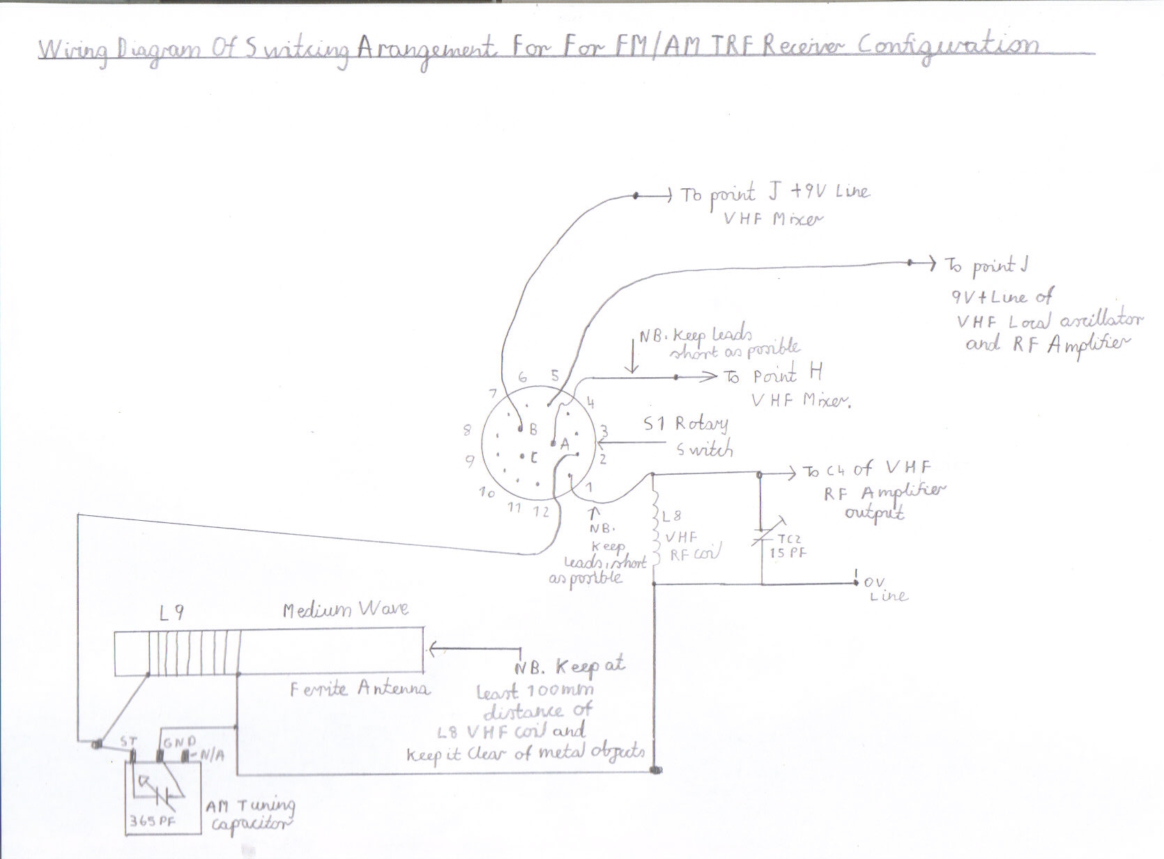
43. Please refer to picture 14 for connection details of the switching arrangement for this configuration.
|
||||
44. If you are now familiar with the wiring diagram of picture 14 you may now go ahead with wiring this stage. Please note the following precautions before proceeding. Mount the S1 rotary switch as close as possible to the VHF mixer input and make sure you keep the wiring of the RF leads as short as possible between the switch and the VHF RF tuned circuit of L8 and TC2, to avoid losses which may result in poor performance of the FM tuner. As a final precaution, make sure you mount the L9 AM ferrite rod antenna as far away as possible or at least 100 mm from the L8 VHF RF coil or its inductance will detune L8 and VHF reception will not be possible. The lead length of the L9 AM ferrite rod antenna from the VC4 tuning capacitor is not critical like the VHF circuits due to the low frequencies involved, but do try to keep this component away from metal objects and for this reason you will have to use a wooden or PVC case to house the receiver. The particular rotary switch used in this configuration is available from Maplin Electronics and it is the 3 Pole 4 Way type. The order code of this component is FF75S. Also the Ferrite rod antenna is also available from the same link as LB12N which will save you having to wind it yourself. Please read the following instructions for wiring up this stage and make sure you have a printed copy of picture 14 to help assist you.
45. Connect point H of the of the VHF mixer input to connection pin A of the rotary switch.
46. Connect the hot end of the L1 VHF RF Coil in parallel with TC2 to Connection pin 1 of the rotary switch
47. Connect the C4 coupling capacitor from the RF amplifier output to connection pin 1 of the rotary switch.
48. Connect the VC4 Tuning capacitor as follows. The moving vanes must be connected to connection pin 2 of the rotary switch and the stator must be connected to the point I 0V line.
49. Connect the high impedance winding of the L9 ferrite rod antenna in parallel with VC4 as shown in the wiring diagram
50. Connect the 9V + positive line of the VHF mixer at point J to connection pin B of the rotary switch.
51. Connect the 9V + positive line at point J of the VHF RF amplifier to connection pin 5 of the rotary switch.
52. Connect the 9V + positive line at point J of the VHF local oscillator to connection pin 5 of the rotary switch.
53. This now completes the wiring configuration of the FM/MW TRF configuration. Please make sure you double check your wiring very carefully as mistakes in the 9V + positive line could cause expensive damage to the FET transistors.
54. If you are now feeling confidant you have wired all these stages correctly you may now prepare to test this configuration.
55. Turn the RV1 IF Gain control to maximum setting.
56. rotate the S1 rotary switch anticlockwise to position 1 which is FM mode.
57. Reconnect the 9V power supply to all stages.
58. The FM section should still work as well as it did before the modification, Except you may have to realign TC2 for maximum signal strength.
59. Rotate the S2 rotary switch clockwise to position 2.
60. Try rocking the VC4 tuning capacitor and it should be possible to tune in a few AM medium wave stations.
61. If the reception sounds very distorted, try turning down the IF gain control until the reception sounds clearer.
62. Rotating the receiver should also improve the weaker stations.
63. As a final note, you will not get the same clarity as FM when using this mode particularly on the weaker stations as electrical interference from computer CRT monitors can be a real problem. There are also still a few ILR stations using split frequencies and do transmit a mixture of 60s 70s and 80s. music. Magic 828 from Leeds is an example which used to transmit as Radio Aire on both bands.
64. It is also possible to wind your own coils for shortwave reception, when using this configuration but be warned that the sensitivity drops off beyond 4.0 MHz 75 metres, so if you are serious about SW then the FM/Shortwave superhet configuration is about the best choice featured next.
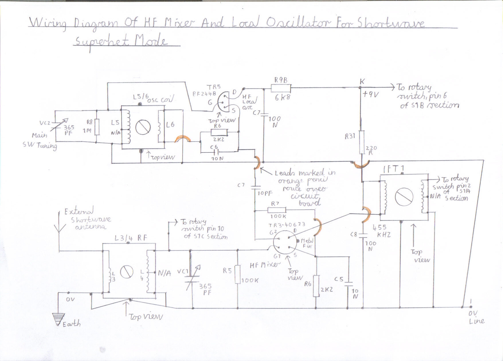
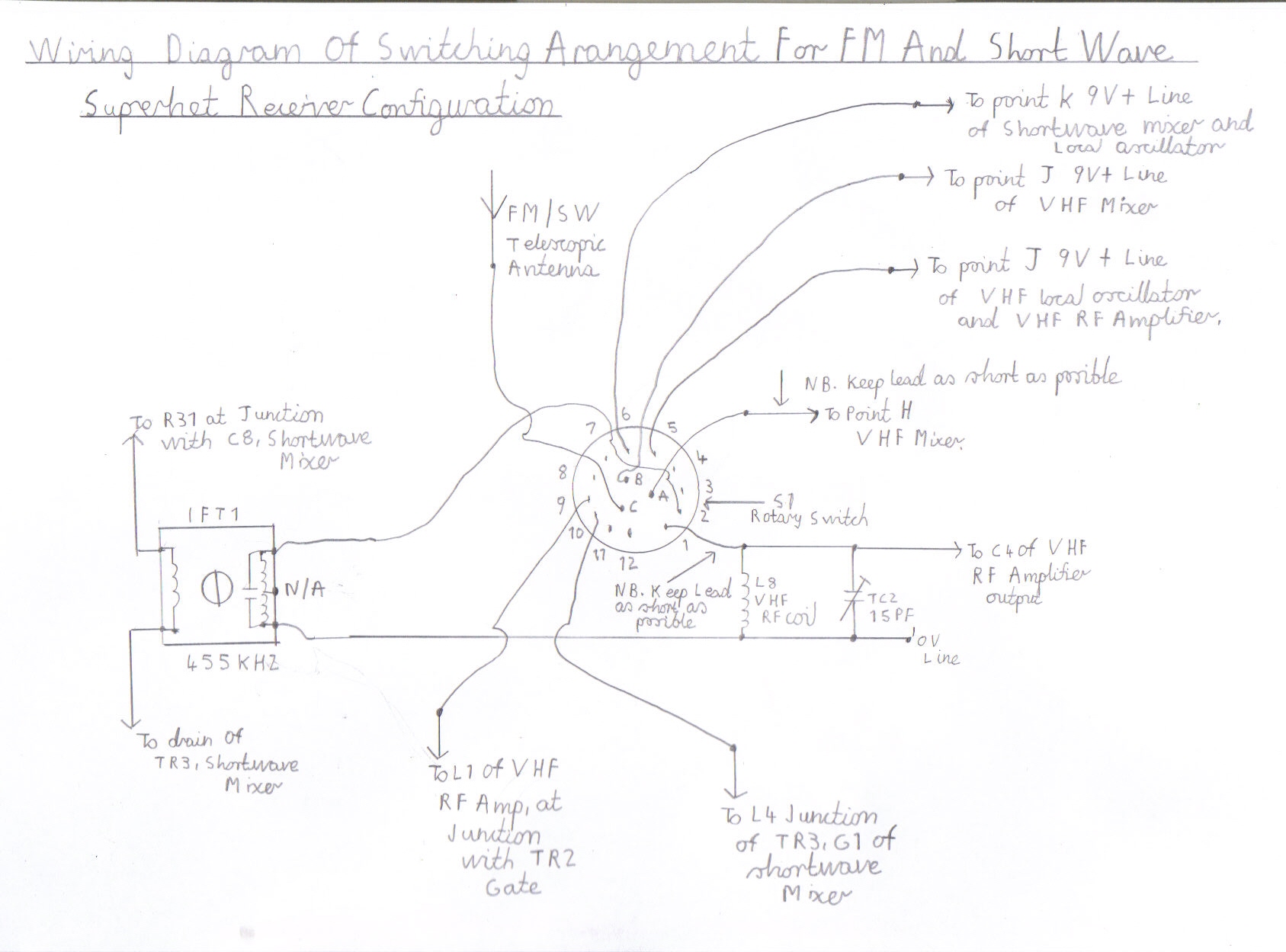
Construction Of The FM And Short Wave Superhet Version Of This Receiver
Like the MW TRF version of this receiver, this configuration uses the same RF input switching arrangement except a 455KHZ IF transformer replaces the MW ferrite rod antenna and a separate HF mixer and local oscillator follows this to form a short wave superhet receiver. This configuration is a bit more complicated regarding the switching arrangement as the 9V positive supply has to be switched from the VHF RF amplifier and local oscillator to the HF mixer and oscillator circuit. Also the telescopic antenna is switched from the L1 RF input of the VHF RF amplifier to the L4 RF input of the HF Shortwave mixer. I would like to strongly advice you on one or two issues regarding component availability before attempting this configuration. Like the difficulty in obtaining IF transformers for valved receivers, I regret to say that it has almost gone the same way for solid state receivers and you may have to part with an old tranie or use alternative coils to the ones tried in this design. The other alternative is to wind your own providing you have the experience. I will briefly describe the ones used in this design. These coils are made by Toko, a Japanese firm and have dealt with transistor RF coils for the last four decades in all commercial radio receivers. Also please refer to the Components List Of AM/FM Pulse Counting Receiver for all other items.
IFT1. YRCS11098AC
L3/L4 RF antenna Coil.
SW1. 1.7 to 5.0 MHZ KANK3333R. SW2. 5.5 to 14 MHZ KANK3334R. SW3. 12.0 to 30.0 MHZ KANK3335R.
L5/6 RF Oscillator Coil.
SW1. 1.7 to 5.0 MHZ KANK3426R. SW2. 5.5 to 14.0 MHZ KANK3337R. SW3. 12.0 to 30.0 MHZ KANK3428R.
SW2 is the best choice out of all the bands as you will obtain world wide coverage at all hours and is the most sensitive of all the ranges. All I can say is that I hope you manage to successfully obtain these coils OK. As my time is tight at the moment I may in the later future try experimenting with home made coils as an alternative and there will be an additional feature. The following links might assist you in obtaining these items but I can not guarantee there full availability. This link http://www.bec.co.uk/ do specialise in Toko coils but it is on a only while stocks last basis on certain hard to get items that are not made anymore. The second supplier on the list is JAB Electronics Toko 10K Coils which may also help you out. Also at the time of writing Antique Electronic Supply sell transistor 455KHZ IF Transformers and they do have a good range of Tuning capacitors that are suitable for both AM/FM sections.
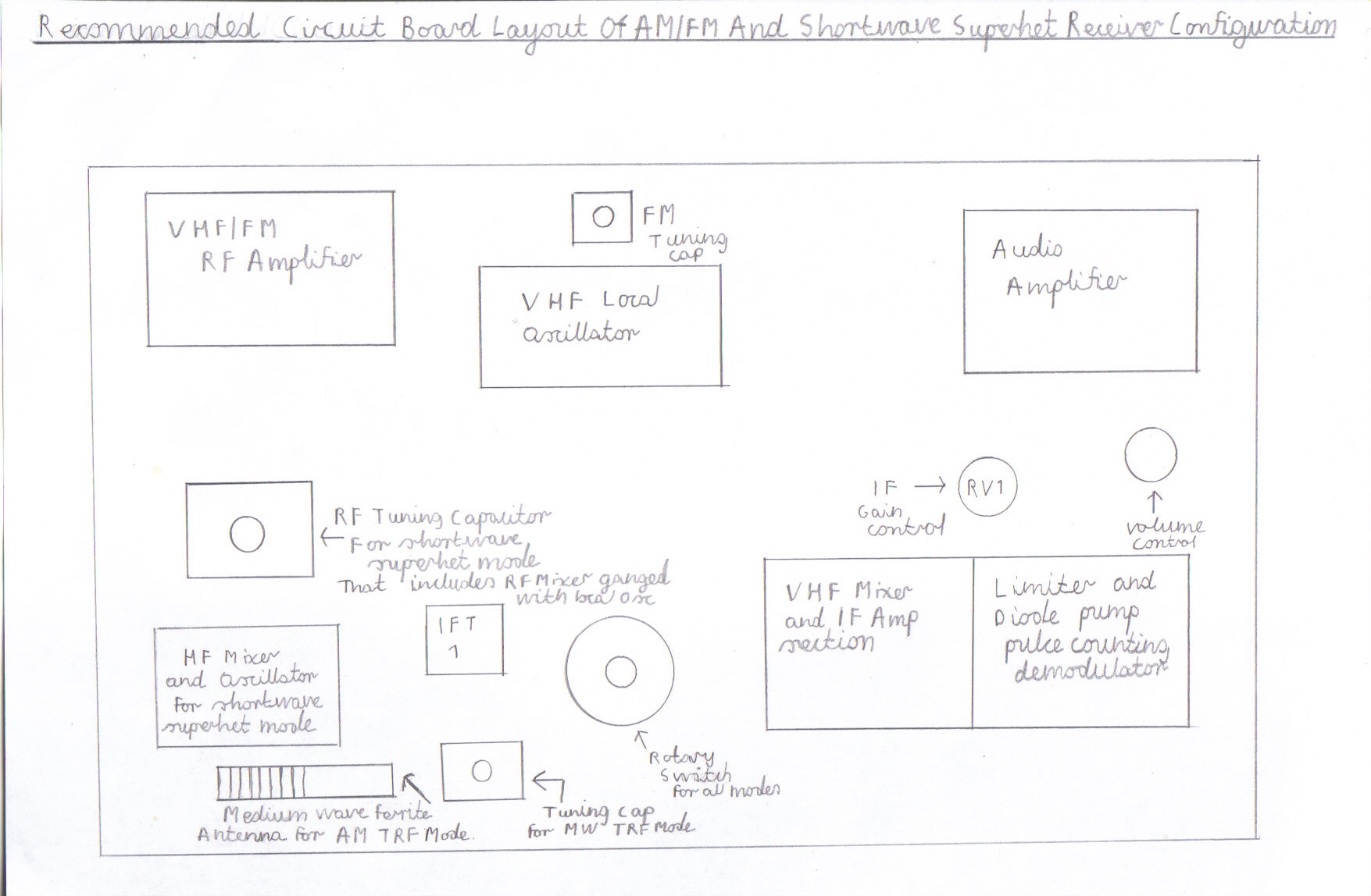
65. Please refer to pictures 15 for the circuit board layout and picture 16 for the circuit diagram. You also need to refer to Components List Of AM/FM Pulse Counting Receiver
|
|
|||
66. As you can see in the in the layout diagram of picture 15 the FM circuitry is in the same order, except the unoccupied space in picture 3 for the FM only configuration now accommodates the rotary switch, the HF RF mixer and local oscillator circuitry for shortwave superhet mode. There are 3 slight modifications concerning the wiring of the FM only version of this receiver that must be carried out before proceeding.
67. Disconnect the 9V + positive line of the VHF RF amplifier from the point J positive 9V + line of the VHF mixer.
68. Disconnect the 9V + positive line of the VHF local oscillator from the point J positive 9V + line of the VHF mixer.
69. Disconnect the L8 RF tuned circuit and C4 coupling capacitor of the VHF RF amplifier from point H of the VHF mixer input. As a final note, make sure you leave the C4 coupling capacitor from the VHF RF amplifier output connected to the hot end of L8.
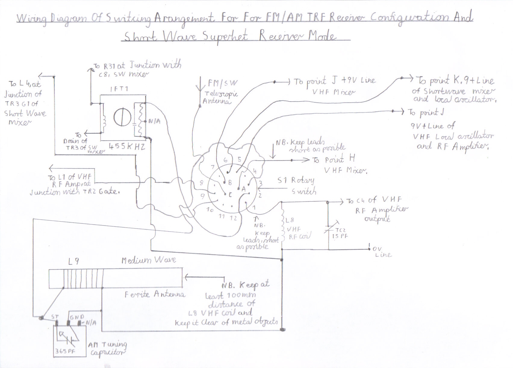
70. Please refer to picture 17 for the wiring diagram of HF shortwave mixer and oscillator circuit
|
||||
71. If you are now familiar with the wiring diagram of picture 17 you can shortly start wiring up this stage but there is 1 issue regarding assembly of certain components on the circuit board that must be taken into consideration first. The S1 rotary switch must be mounted as close to the point H VHF mixer input as close as possible, leaving room to accommodate the L8 VHF RF coil and TC2 trimmer to reform the VHF tuned circuit. IFT1 is mounted on the left opposite side of the rotary switch. The wiring precautions regarding this stage is the same as for the VHF circuits, except due to lower frequencies the lead lengths are not as critical but do try to keep them as short as possible particularly if you intend to use the SW3 12 to 30 MHZ coil range. It is also possible to use band switching in this section but you must remember that the performance regarding frequency stability may slightly impair due to longer lead lengths involved and you must try to wire it in a way that shortest wiring goes to the SW3 range, particularly the L5 and L6 local oscillator coils. All components including the FET transistors are top views and as said before make sure you observe the correct polarity of these components. Separate RF and tuning capacitors have been included to make the alignment of this stage easier and you can use another SW receiver to help assist you but an RF signal generator may be a great help as newcomers to shortwave, will not be familiar with these crowded wavelengths in finding there way around, like the FM and AM medium wavebands. Ganged Tuning is also possible, which is less expensive and more convenient except separate RF trimmers will be needed to ensure correct tracking which will make the alignment procedure more difficult. If you are now confident you have wired everything correctly regarding this stage please refer to picture 18 for the wiring of the S1 rotary switch.
|
||||
72. Before proceeding it is advisable to have a printed copy of picture 17 and picture 18 to help assist you with the wiring of this stage. Please read the following instructions very carefully as serious wiring errors particularly in the 9V positive line may damage the FET transistors and burn up the tuned winding of IFT1, if a positive 9V to 0V voltage is accidently applied to this component.
73. Connect point H of the VHF mixer input to connection pin A of the rotary switch.
74. Connect the hot end of the L1 VHF RF Coil in parallel with TC2 to connection pin 1 of the rotary switch.
75. Connect the C4 coupling capacitor from the VHF RF amplifier output to connection pin 1 of the rotary switch.
76. Assuming you have already connected one side of the IFT1 tuned winding to 0V when wiring up the HF mixer, connect the hot end of IFT1 to connection pin 2 of the rotary switch.
77. Connect the 9V + line of the VHF mixer at point J to connection pin B of the rotary switch.
78. Connect the 9V + line at point J of the VHF RF amplifier to connection pin 5 of the rotary switch.
79. Connect the 9V + line at point J of the VHF local oscillator to connection pin 5 of the rotary switch.
80. Connect the 9V + line at point K of the HF Shortwave mixer and oscillator to connection pin 6 of the rotary switch.
81. Connect the VHF RF amplifier input, that is at the junction with L1 and TR2 Gate to connection pin 9 of the rotary switch.
82. Connect the L4 RF Mixer coil of the shortwave mixer, that is at the junction with TR3 G1 to connection pin 10 of the rotary switch.
83. Connect the AM/FM telescopic antenna to connection pin C of the rotary switch.
84. This now completes the wiring regarding the FM and Shortwave superhet configuration and would advice you to double check your work for any possible mistakes before proceeding with the next stage, which is the initial testing and setting up of this configuration.
85. Turn the RV1 IF Gain control to maximum setting.
86. Rotate the S1 rotary switch anticlockwise to position 1 which is FM mode.
87. Reconnect the 9V power supply to all stages.
88. FM should still work as well as it did before the modification, except you may have to realign TC2 for maximum signal strength.
89. Now for the big moment. Rotate the S2 rotary switch clockwise to position 2 and fully extend the telescopic antenna.
90. Try rocking the VC2 tuning capacitor and it might be possible depending on what part of the shortwave spectrum you are tuning, be able to tune a few stations. If this is so, try rocking VC1 for maximum signal strength. Also if reception sounds very unintelligible and distorted try turning down the IF gain control until reception sounds clear.
91. Band conditions on shortwave depend on the time of day and you will find during the summer months that frequencies between about 10.MHZ to 22MHZ are active around the clock but during the winter they fade out around early evening usually after dark until sunrise the next day. Frequencies between 4.0 to 9.0 MHZ have the best worldwide coverage of all after dark, virtually all year round and you may find reception is at its lowest during the late hours of the morning, only to start peaking up again around mid afternoon.
92. To get the best out of shortwave, a proper long wire outdoor antenna is advisable and this must be connected to the L3 Antenna coupling winding rather then simply connecting it to the L4 tuned winding because this can result in mixer overloading and out of band cross modulation. Also lowering the IF gain may help as well as adding a simple attenuator at the antenna input that can simply be a 1K Linear Potentiometer.
94. Before I go through the alignment instructions for this configuration I will just briefly describe the FM/TRF and Shortwave superhet all mode version which is basically the same as this configuration but has the MW TRF mode facility included .
Construction Of The All Mode FM/MW TRF And Shortwave Superhet version of this Receiver
This configuration requires very little comment because the circuitry is the same as the FM and shortwave superhet version described previously. The only components required is a simple ferrite rod antenna and tuning capacitor wired to connection pin 3 of S1 and the 0V line. The alignment is also the same as the FM and Medium Wave TRF version. Please refer to pictures 19 to 21.
|
|
|
||
95. The only precaution I will remind you of is make sure you have enough room beside the HF mixer and oscillator to accommodate the tuning capacitor and medium wave ferrite rod antenna as shown in picture 19. Also be careful to mount the ferrite rod antenna at least 100mm away from the L8 VHF RF Coil.
Alignment Of The HF Mixer And Oscillator For Shortwave Superhet Mode
96. You must make sure you use the correct RF Nylon or PVC trimming tools for aligning the RF coils. Using screwdrivers or any other metal tool will simply detune the circuits when removed and could also fracture the delicate cores.
97. As there is only 1 IF tuned circuit involved in this design, IFT1 can be simply left as it is.
98. Try Tuning VC2 to the middle of the band concerned, that is with the vanes advanced around half way open and peak the VC1 Mixer trimmer for maximum signal strength.
99. Repeat the same step as 98 but try tuning to the low frequency end of the tuning range, that is with VC2 vanes nearly closed.
100. Try peaking the L3/4 RF coil for maximum signal strength.
101. Repeat the last 2 steps except try tuning to the high frequency end of the tuning range, that is with VC2 vanes almost fully closed.
102. Adjusting the core of the L5/6 oscillator coil anticlockwise gives you extended high frequency coverage at the lower frequency end of the tuning range and an RF signal generator may be required to correct this or a second receiver that tunes around the same frequency in question may surface but may be more time consuming.
Finally
I hope you all successfully manage to locate the hard to get components ok for this superb AM/FM receiver project and hope you enjoy the simple technique of enjoying both modes while it is still alive without having to go though all these silly new ideas of DAB Radio and it is the same old saying, You use it or lose it so the more we construct these sort of projects the longer it will stay with us.
Links To My Other FM Receiver And Hi Fi Projects
Transistor Pulse Counting FM Receiver
Double Conversion Pulse Counting FM Superhet Receiver With 10.7 MHZ First IF Stage
Single Conversion 6 Transistor 10.7 MHZ Pulse Counting Receiver, Designed For Stereo FM Reception
6 Valve VHF/FM Pulse Counting FM Tuner Using Safe 25Volt DC HT Line
Valve Version Of The 10.7 MHZ Double Conversion VHF/FM Pulse Counting Tuner
3 Valve 3 Watt Stereo Amplifier
Simple Stereo Preamplifier Circuits For The 3 Valve Stereo Amplifier
Site Map Of All My Webpages And Favourite Valve Radio Related Links