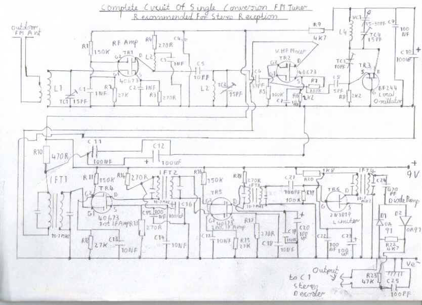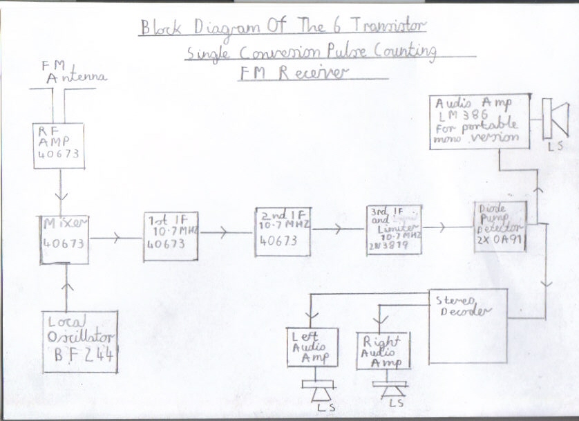
Single Conversion 6 Transistor 10.7 MHZ Pulse Counting Receiver, Designed For Stereo FM Reception With The Existing Stereo Decoder Circuit
Welcome to this 3rd feature of my transistor FM receivers. This is an unusual design of the pulse counting FM receiver as it uses a the standard 10.7 MHZ Intermediate Frequency which may seem a bit to high compared to the low frequency IF used in commercial and my previous receiver designs. This is compensated for by using a 2 stage dual gate FET IF amplifier and a single channel FET Limiter to follow the diode pump voltage doubler detector resulting in very high gain. This receiver due to the high IF response, gives excellent stereo separation when fed to the new FM Stereo Decoder Circuit which it is designed for and is highly recommended for constructers wanting a stereo design. It also serves well as an excellent mono portable receiver and will drive a LM386 just nicely with no instability when using a single 9 volt battery supply. This design has been tried with the foster Seeley discriminator, but due to the low sensitivity which would have led to extra audio preamplification and due to the scarce availability of centre tapped 10.7 MHZ transformers I decided the diode pump pulse counting detector has won and despite the high IF it still gives very good audio quality.
Construction Details Of This Receiver
Please refer to the pictures below for circuit information and construction details of this FM Receiver.
|
|
|
|
|
|
|
|
|
|
Please left click on selected picture to enlarge image
Step 1 of building procedure
Please make sure you have all the components available at hand before even attempting to build this receiver by clicking on the following link Components List Of Single Conversion FM Receiver . Please also bear in mind that some of the components called for in the list may not be easily available such as the IF transformers and transistors. Suitable alternatives may have to be sorted if this is the case. This receiver is also built in a back to back sequence which I will briefly explain. Instead of starting from the front end stages it starts from the Audio and follows right up to the mixer and RF amplifier section. This is by far the easiest and best method of constructing superhet receivers as you can test and align each stage as you build it. You can also correct faults more easily because if the last stage works ok and the following stage does not work, it is that stage that has the problem and needs to be corrected before proceeding with the next stage. Also the interstage connections in the wiring diagrams are in alphabetical sequence of A to Z to help identify the connections in each stage and helps to avoid mistakes.
Step 2 Construction level and experience required
Owing to the fact that there are step by step simple diagrams featured in this design any one who has had experience in building a Medium Wave superhet receiver or my Severn Valve HF Superhet Receiver Designed For Advanced Constructors should find little difficulty but I would just like to make one point clear before proceeding. VHF circuits require a lot more skill then the long wire approach of medium wave and short wave receivers particularly in the frequency changer, oscillator and RF circuits. As every millimetre of lead counts as an inductance, long leads at these frequencies can lead to poor performance particularly at the high end of 102 MHZ around Classic FM and for the same reason don't even attempt to try incorporate band switching. If you wish to have it as a multiband set then I would suggest you build a separate converter for the band concerned which would mean extra expense and you would still have to use hot switching in the positive lead for each converter plus you would have to modify the IF stages to work at 455KHZ as well. This technique was used on the old FM transistor portables of the 1960s and 70s.
Step 3 Special precautions regarding the components and batteries
As many electronic constructors of the valve era who moved on to semiconductors will tell you, they are nowhere near as rugged as valves regarding wrong mistakes in the connections and also they are very heat and static sensitive, particularly the field effect transistors used in this design. You must therefore use an antistatic mat and whist strap connected to the mains earth by a 1 megaohm resistor. This precaution is not needed for valve circuits and can result in a fatal electric shock to earth, so only use it on a temporary measure when constructing solid state circuits involving static sensitive components. You must also take care when soldering these sensitive components, to try not apply the soldering iron for more then 5 seconds, that is allowing just enough time to make a clean shiny joint and a pair of tweezers designed for this job is highly recommended as it shunts away heat along with a 25 Watt soldering iron. Although battery operated circuits are much more safer to experiment with then high voltage valve circuits there are a few other precautions to bear in mind. As the old Eveready and Excide Zink carbon batteries are now getting very hard to get hold of, there are new dangers on the horizon to be aware of. We now need to use the Duracell alkaline type batteries and as these deliver a more heavier current you must be very careful not allow a continues short circuit to happen or there is the severe risk of leakage or explosion. Also take care regarding the polarity of the batteries making sure the red lead corresponds to the positive + line and black lead to the negative - line. Also pay attention to the polarity of the electrolytic capacitors as these can also be permanently damaged also resulting in explosion. The Germanium diodes in the discriminator circuit are also very heat sensitive and must be connected in the right polarity or the circuit will not function correctly. If you follow these simple precautions very carefully you should have some very happy hours building this superb FM Receiver project.
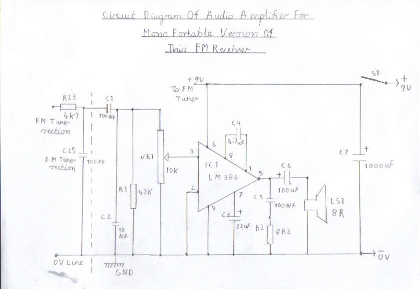
Step 4. The Audio amplifier and De-emphasis circuit. NB Applies to mono version only or battery portable stereo receiver
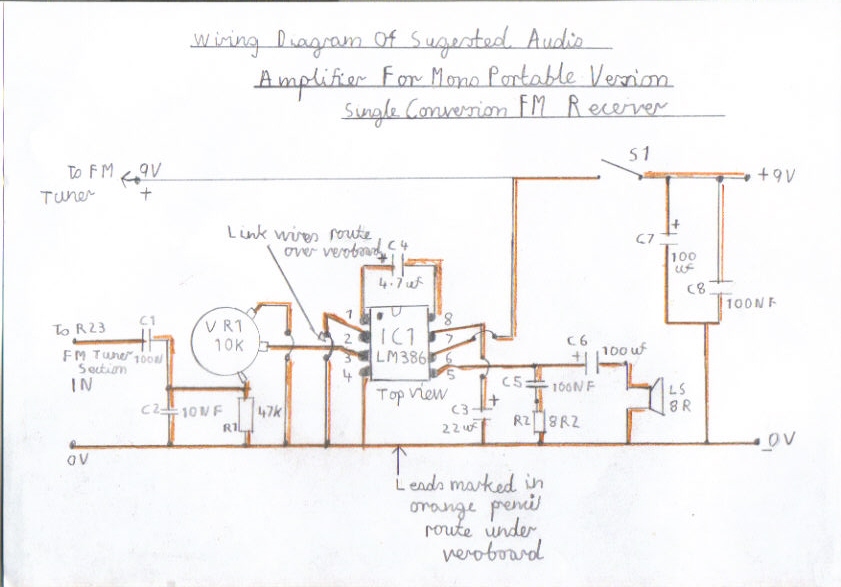
If you are wanting a mono portable version of this receiver you need to refer to picture 3 which is the wiring diagram of the suggested amplifier circuit and must be constructed and tested first. If you want a FM Stereo tuner version of this receiver you must skip this step and proceed to step 4 and also resort to the link FM Stereo Decoder Circuit . If you want a stereo portable version of this receiver you will need 2 versions of the suggested amplifier circuit and you also need to omit the following components C1, C2, R1 and connect the left and right channel signal outputs from the decoder circuit to the VR1 signal input on each individual amplifier. Special warning regarding the use of other low powered IC amplifiers. The LM386 circuit featured is recommended and has been found to be the most stable IC for all my FM Radio designs. Circuits that are to be avoided with this design is the TDA7052 and TBA820M. I have found them to be very unstable resulting in severe VHF parasitic oscillation. However. I will later be featuring a 9 Volt mains power supply unit for this receiver and the decoder circuit, which might make these ICs mentioned, more stable which I think lies down to battery decoupling. Valve amplifiers also work very well with this tuner and if you intend to connect to a mono valve amplifier C1 must be rated at least around 400V for safety reasons. NB. Do not connect to a valve amplifier that is of the AC/DC type that incorporates a live chassis or a serious electric shock hazard will exist. Please refer to picture 3 regarding construction of the audio amplifier and pay particular attention regarding the polarity of certain components such as the electrolytic capacitors. You must use a 8 PIN IC holder for the LM386 as it is very heat sensitive and make sure that the half-moon shaped notch or corner dot corresponds as shown in the wiring diagram. All wiring diagrams for this design are top views and leads that are marked in orange must route under the Veroboard. The leads marked in black pencil are link wires and are supposed to route over the top of the Veroboard. If you are confidently sure you have checked the wiring very carefully you may now test this amplifier circuit.
1A. Connect a 8 Ohm speaker to the output.
2A. Connect a suitable 9 Volt battery supply preferably a 9 Volt PP3 Zinc carbon when first testing or a power supply with a current limiter incorporated.
3A. Switch on and if all is well you should hear a quite hiss in the speaker.
4A. Rotate VR1 clockwise and touch the input at VR1 with your finger.
5A. If you hear a buzzing noise this means you have got the amplifier working correctly.
6A. If all the above procedures have gone to plan you can now proceed to step 5.
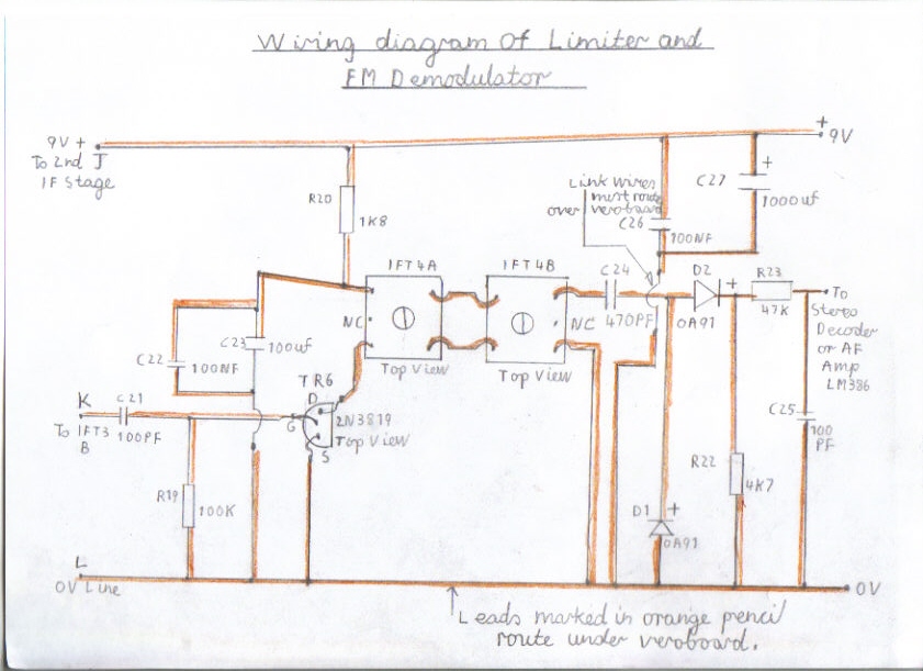
Step 5. The FM Demodulator And Limiter
Please refer to picture 4 for the the wiring diagram of the Limiter and FM Demodulator circuit. You need a Signal generator that is capable of covering the 10.7 MHZ IF frequency, Preferably FM modulated although AM will be suitable. You must also use the correct nylon trim tools for aligning the IF transformers as using metal screwdrivers will detune the IF circuits and could also crack these delicate cores. Pay particular attention to the polarity of the germanium diodes making sure the red positive cathode end corresponds as shown in the diagram and the correct orientation of the 2N3819 Field Effect Transistor. Also pay particular attention to the polarity of the electrolytic capacitors C22 and C27. Before building this stage please refer to the following instruction steps.
1B. Start by building backwards from the the FM Demodulator stage.
2B. Only wire as far as up to IFT4A for the time being and don't yet insert R19 R20 C21 C22 C23 and TR6.
3B. Connect the output from the FM Demodulator to a suitable audio amplifier.
4B. Do not under any circumstances connect the 9V + line as this is not yet needed and is for the simple reason that C27 will still be charged due to no load when the line is disconnected, resulting in the TR6 FET transistor being destroyed during soldering if this precaution is ignored.
5B. You now need to refer to picture 9 which gives you a diagram of the alignment procedure and is used on each IF stage up to the VHF mixer.
6B. Connect the signal generator as shown making sure you connect the red test probe to the top left hand side terminal of IFT4A. Next you need to connect a temporary short link wire from the bottom left hand side terminal of IFT4A to the 0 Volt line to form a temporary earth. NB This step is also repeated when aligning all IF stages in this receiver until you get to IFT1A of the VHF mixer. You must also remember to remove the temporary link when when you finish aligning each IF stage.
7B. Connect the black probe to the 0 Volt line.
8B. Set the signal generator to tone modulation
9B. Tune around the 10.7 MHZ region until you hear a modulated tone.
10B. If this is so try adjusting the cores of IFT4B and IFT4A for maximum signal strength
11B. If the setting of your signal generator seems to be way off the 10.7 MHZ Frequency when you receive the modulated tone, say for example 12 MHZ this needs correcting.
12B. For example. If you a getting the modulated tone on 12 MHZ try very slowly adjusting IFT4B clockwise until the tone starts to decrease. Do the same with IFT4A until the tone gets slightly fainter. Retune the signal generator until the modulated tone increases. If you are now hearing the modulated tone at 11 MHz repeat the same step very slowly until you get the IF frequency down to 10.7 MHZ and adjust each core for maximum signal Strength. If you find the Frequency is lower at about 9 MHZ you need to do this procedure in the reverse direction adjusting both cores anticlockwise.
13B. If the above tests have gone to plan you may now wire up the rest of the components in this stage. Please take special care when soldering the TR6 Field Effect transistor making sure you follow the precautions mentioned in step 4 and making sure the flat side corresponds correctly as shown in the wiring diagram.
14B. This stage can not yet be tested properly until IFT3B and IFT4A have been installed and connected to points K and L. You now need to proceed to Step 6.
Step 6. The IF Amplifier Stages
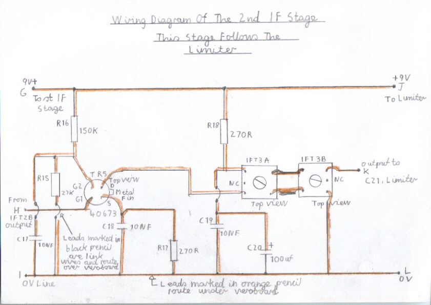
1C. Please refer to picture 5 for the wiring diagram of the 2nd IF Amplifier.
2C. Install and wire IFT3B and IFT3A as shown in the wiring diagram. Do not yet, wire in the following components R15 R16 R17 R18 C17 C18 C19 C20 TR5.
3C. Connect the Right top terminal of IFT3B at point K to C21 of the limiter.
4C. Connect the bottom right hand terminal of IFT3B to the 0 Volt line at point L to the limiter.
5C. At this point please check your work very carefully for wrongly placed components and dry soldering joints.
6C. If you are confidant everything is OK connect a suitable 9 Volt power supply to the junction C26 and C27 of the limiter observing the correct polarity.
7C. Repeat the alignment instructions step from 5B to 12B for IFT3B and IFT3A.
8C. If you find you are experiencing self oscillation when peaking these trimmers to maximum you will need to back off the adjustment slightly. This is normal when building all superhet receivers. However. don't confuse this oscillation with the normal background static hiss you get from the FM demodulator as you tune between stations.
9C. If all has gone well with the alignment procedure of the limiter you may now wire up the rest of the 2nd IF amplifier stage. Please take special care when soldering TR5, handling the leads as little as possible and make sure you follow the antistatic precautions very carefully. If you are using the original 40673 Dual gate FET, It does have built in protection diodes. Please also make sure the metal square fin on the right bottom side of this device corresponds correctly as shown in the diagram.
10C. Do not at this moment connect the 2nd IF stage to the 9V + line as TR5 may be damaged due to no Gate Bias until IFT2B and IFT2A has been installed.
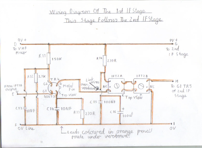
11C. Please refer to picture 6 for the wiring diagram of the 1st IF Amplifier.
12C. Install and wire up IFT2B and IFT2A as shown in the wiring diagram. Do not yet, wire in the following components. C13 C14 C15 C16 R11 R12 R13 R14 TR4.
13C. Connect the top right terminal of IFT2B at point H to G1 of TR5.
14C. Connect the bottom right terminal of IFT2B at point I to the 0V line.
15C. If you are confident you have checked all wiring very carefully at this point, connect the 2nd IF stage at Point J, to the positive + 9 Volt line.
16C. Repeat the alignment step from 5B to 12B for IFT2B and IFT2A.
17C. If all has gone well with the alignment of the 2nd IF stage you may now wire up the rest of the components of the 1st IF amplifier taking the same precautions as previously mentioned for the 1st IF stage.
18C. Do not at this moment connect the 1st IF stage to the positive + 9 Volt line.
19C. Please refer to step 7 for instructions on testing this stage and construction details of the VHF Mixer and local oscillator stage.
Step 7. The VHF Mixer And Oscillator
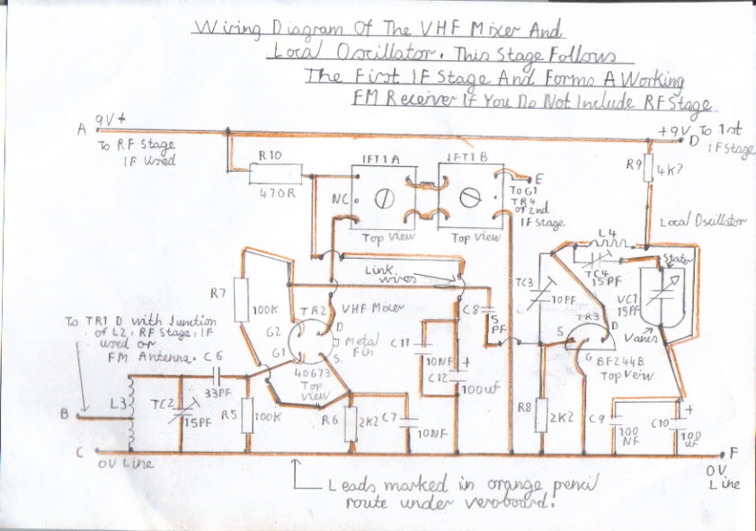
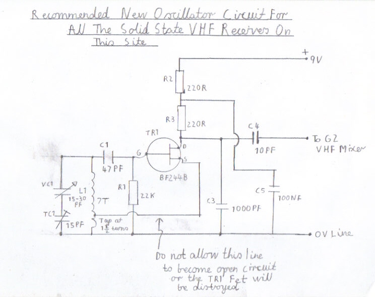
1D. Please Refer to picture 7 for the wiring diagram of the VHF mixer and local oscillator stage.
2D. Install and wire up IFT1B and IFT2A as shown in the wiring diagram. Do not wire up the rest of these stages at this moment as there is still testing of the 1st IF stage to be completed followed by special precautions regarding the wiring of the VHF mixer and oscillator stages.
3D. Connect the top right terminal of IFT1B at point E to G1 of TR4.
4D. Connect the bottom right terminal of IFT1B at point F to the 0 Volt line.
5D. If you are again, confident that you have checked all wiring very carefully at this point, connect the 1st IF stage at point D to the positive + 9 Volt line.
6D. Repeat the alignment step from 5B to 12B for IFT1B and IFT1A.
7D. If all has gone well with the alignment and testing of the IF amplifier circuits it is now time to wire up the VHF mixer and oscillator circuits.
8D. This is where great precautions in the circuit layout must be taken as the risk of poor performance is very high due to a much higher frequency being used then with medium wave and short wave superhet receivers. Even these receivers can suffer similar problems particularly at the top end of the HF band spectrum between 15 to 30MHZ. Short and direct wiring of the tuned circuits must be the order of the day in these circuits with no double earths and try not to cram the mixer and oscillator circuits close together. It may be possible to build the local oscillator in a separate metal box with the advantage of less RF radiation resulting in better stability. If you decide to use a metal case there is just one more precaution I must remind you of. Because VC2 is at positive potential in respect to earth, You must make sure that the metal spindle does not come in contact with the case or there will be a short circuit preventing the local oscillator from working. A spindle coupler with a nylon rod is also a good idea to include as this will keep hand capacity effects at an absolute minimum preventing nuisance detuning effects.
9D. If you followed the above precautions very carefully you may now go ahead with the wiring of the VHF mixer and oscillator circuits. The RF coils L3 and L4 are self supporting about 10mm diameter and are wound with about 7 turns of 16 SWG Enamelled copper wire and must be soldered onto Vero pins rather then permanently wiring on to the circuit board, so modification regarding frequency coverage can be carried out at later stage if needed. The UK 2.5 size ring mains cable is also an excellent alternative as the solid copper conductors can be striped down. Like I have mentioned previously, take care when soldering the field effect transistors.
10D. If you are at this stage very confident you have constructed this stage correctly then you could be in for the exiting moment of truth.
11D. Please refer to step 8 for alignment details of the VHF circuits.
Step 8. Alignment Of The VHF Mixer And Oscillator Circuits
The alignment of this receiver is almost the same as my Double Conversion Pulse Counting FM Superhet Receiver With 10.7 MHZ First IF Stage and the local oscillator can be aligned 10.7 MHZ above or below the desired reception frequency. For this design I prefer to run the local oscillator at 10.7 MHZ above the reception frequency. Suppose we want to cover the entire FM band between 87.5 MHZ to 108MHZ. The local oscillator must tune between 98.2 MHZ to 118.7 MHZ. However. Because of the scarce availability of dual gang variable capacitors that are suitable for VHF, this receiver will only tune satisfactory between 87.5 to 102 MHZ when using a single gang tuning capacitor. The mixer trimmer TC2 is tuned to about the centre of the FM band to give the best performance. Please refer to the steps below for tuning and aligning the VHF circuits.
1E. Connect the VHF mixer and local oscillator circuits at point D to the 9 Volt + positive line.
2E. Loosely couple about 1 metre of insulated copper wire to L3 or solder about 2 turns from the earthy end of the coil. Better still, an indoor dipole or outdoor FM antenna.
3E. Rock the VC1 tuning capacitor in both directions and you may if you are in luck be able to tune in a few FM stations.
4E. If this is so adjust TC2 for Maximum signal strength.
5E. Try to locate BBC Radio 2 which is broadcast between 88 to 91 MHZ.
6E. If you are receiving Radio 2 with the VC1 tuning capacitor vanes half way open this needs to be corrected.
7E. To correct this you need to refer to TC4 which is the oscillator trimmer.
8E. Closing the vanes of TC4 increases the capacitance of VC1 or opening the vanes of TC4 decreases the capacitance of VC1
9E. In the case of receiving Radio 2 with the vanes of VC1 half way open you now need to slowly close the vanes of TC4.
10E. Try retuning Radio 2 by closing the vanes of VC1 anticlockwise.
11E. Keep repeating these steps until you can receive Radio 2 with the vanes partly open around 3mm.
12E. If this is so try tuning further up the FM band by slowly opening the vanes of VC1.
13. You may find that you can tune in Radio 2 again followed by the rest of the FM band as you have opened the vanes of VC1 half way. This again needs correcting which I will tell you the simple reason. You are affectively tuning the local oscillator between 77.3 to 118 MHZ which means the local oscillator is tuning 10.7 below the reception reception frequency. In the case of you receiving the same stations again as you open the vanes of VC1 from midway you are now tuning the local oscillator 10.7 above the reception frequency which is what we want.
14E. To correct this problem you need to repeat step 7E to 12E until you can tune the entire FM band from 87.5 to about 102 MHZ.
15E. TC3 is the local oscillator feedback trimmer and if you find the oscillator is dropping out when tuning certain parts of the tuning range you may have to readjust this trimmer. Having the vanes of this trimmer half way open should be satisfactory as a starting point
16E. If all the above steps have gone ok regarding the alignment of the correct frequency coverage you must now proceed to the final RF alignment.
17E. Try tuning in a strong local station around the middle of the FM band, somewhere around 95.9 MHZ.
18E. Adjust TC2 for Maximum signal strength.
19E. Try tuning further up towards the entire end of the band around 101 MHZ until you pick up a reasonably strong station such as Classic FM. Readjust TC2 for maximum signal strength.
20E. Repeat these last 3 steps in the reverse direction until you can tune in Radio 2 on about 89.3 MHZ.
21E. Readjust TC2 for Maximum signal strength.
22E. You may have to repeat several times until you can receive satisfactory performance throughout the entire FM Band.
23E. It may be necessary to slightly realign the IF stages if you are finding reception weaker then normal, even when you are using an outdoor antenna.
24E. If this is so, adjust IFT4B at the discriminator carefully in both directions until signal strength improves.
25E. Do the last step with all IF transformers in the reverse direction working your way towards IFT1A at the VHF mixer and there should be a massive improvement in signal strength.
26E. If at any time when you peak the IF transformers, experience oscillation, try backing off the core from there maximum peak slightly.
27E. If all the alignment procedures have gone well to plan you should now have a working FM tuner that is capable of giving excellent performance and suitable for HI FI Stereo Reception.
28E. The performance of this set can be improved further more by adding an RF amplifier stage ahead of the mixer and is also recommended for the following reasons. It improves the signal to noise ratio, essential when receiving stereo transmissions and gives the added protection against radiation of the local oscillator coursing illegal interference.
29E. Please refer to step 9 for construction of the RF amplifier if you intend to build this stage.
Step 9. RF Amplifier
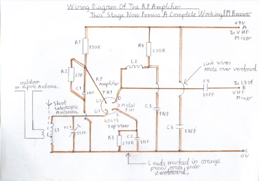
1F. The RF Amplifier stage is very simple and in fact it uses the same circuit design as the rest of all the IF stages. Although this FM Receiver gives excellent performance without this stage it allows this design to give superb stereo performance when using short indoor antennas on strong national broadcasts and acceptable reception on weak distant stations. It also has the advantage of improved image response and isolation of RF radiation from the local oscillator and saying that, the risk is very low due to the oscillator running 10.7 MHZ above the frequency. Please refer to picture 9 for the wiring diagram.
2F. Like the construction of the VHF mixer and local oscillator stages, it is the same procedure making sure that you keep all wiring short and no double earths.
3F. The coils are also constructed in the same manner as the VHF mixer and local oscillator circuits with the same number of turns and diameter of wire.
4F. If you are confident you have wired everything regarding this stage correctly you can now test this final part of the construction stage.
5F. Connect the RF Amplifier at point A to the 9 Volt + positive line.
6F. Connect the RF Amplifier output at point B to about the centre tap of L3 of the VHF mixer or 2 turns from the earthy end of L3 Coil as a start.
7F. Connect the RF Amplifier at point C to the 0V earth line.
8F. Loosely Couple about 1 metre of insulated copper wire or a decent outdoor antenna to L1 RF coil.
9F. The alignment procedure is very much the same as the VHF mixer and it is just a matter of adjusting the TC1 Trimmer for maximum signal strength on all the entire FM band. You should be able to receive the same stations as before but with much improved signal strength and less background hiss when receiving stereo transmissions from distant stations.
10F. This now completes the construction of this receiver and is my last of solid state FM receiver projects for the time being as I have a lot of my valve designs to catch up with. I wish you all the success in building this design and hope we have many years to come of enjoying FM stereo before its to late due to the digital invasion of DAB.
Links To My Other FM Receiver And Hi Fi Projects
Transistor Pulse Counting FM Receiver
Double Conversion Pulse Counting FM Superhet Receiver With 10.7 MHZ First IF Stage
6 Valve VHF/FM Pulse Counting FM Tuner Using Safe 25Volt DC HT Line
Solid State AM/FM Pulse Counting Receiver
Valve Version Of The 10.7 MHZ Double Conversion VHF/FM Pulse Counting Tuner
3 Valve 3 Watt Stereo Amplifier
Simple Stereo Preamplifier Circuits For The 3 Valve Stereo Amplifier
Links To My Video Clips Of This Receiver Working
My Single Conversion FM Receiver Working In Stereo - YouTube
Site Map Of All My Webpages And Favourite Valve Radio Related Links