3 Valve Regenerative Superhet Receiver
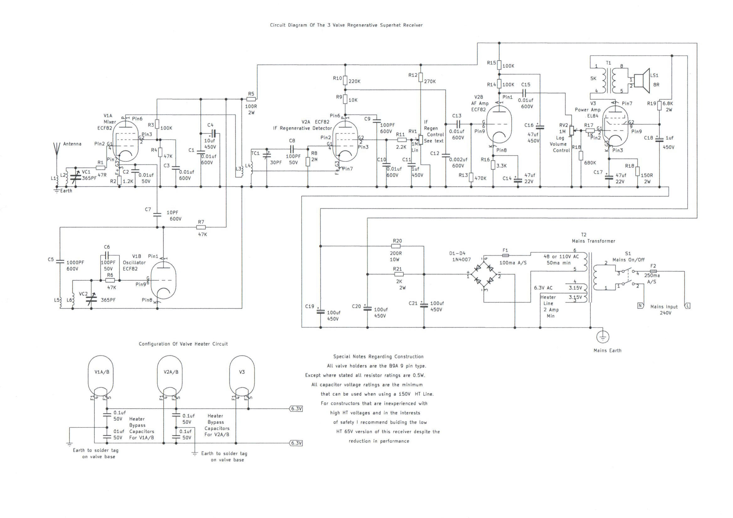
Welcome to this part of my site which features construction details for a 3 Valve Regenerative Superhet Receiver. It is basically an add on circuit of a frequency changer connected ahead of my Simple 2 Valve Regenerative Receiver NB This is an old article being updated which was originally details of just the superhet converter circuit. Allow around mid April to early May for full completion.
|
|
|
|
|
Please left click on selected pictures to enlarge image.
Constructing This Receiver
More details to follow soon as this is an updated article as part of the new revamp of this website
Constructing And Winding The RF Coils
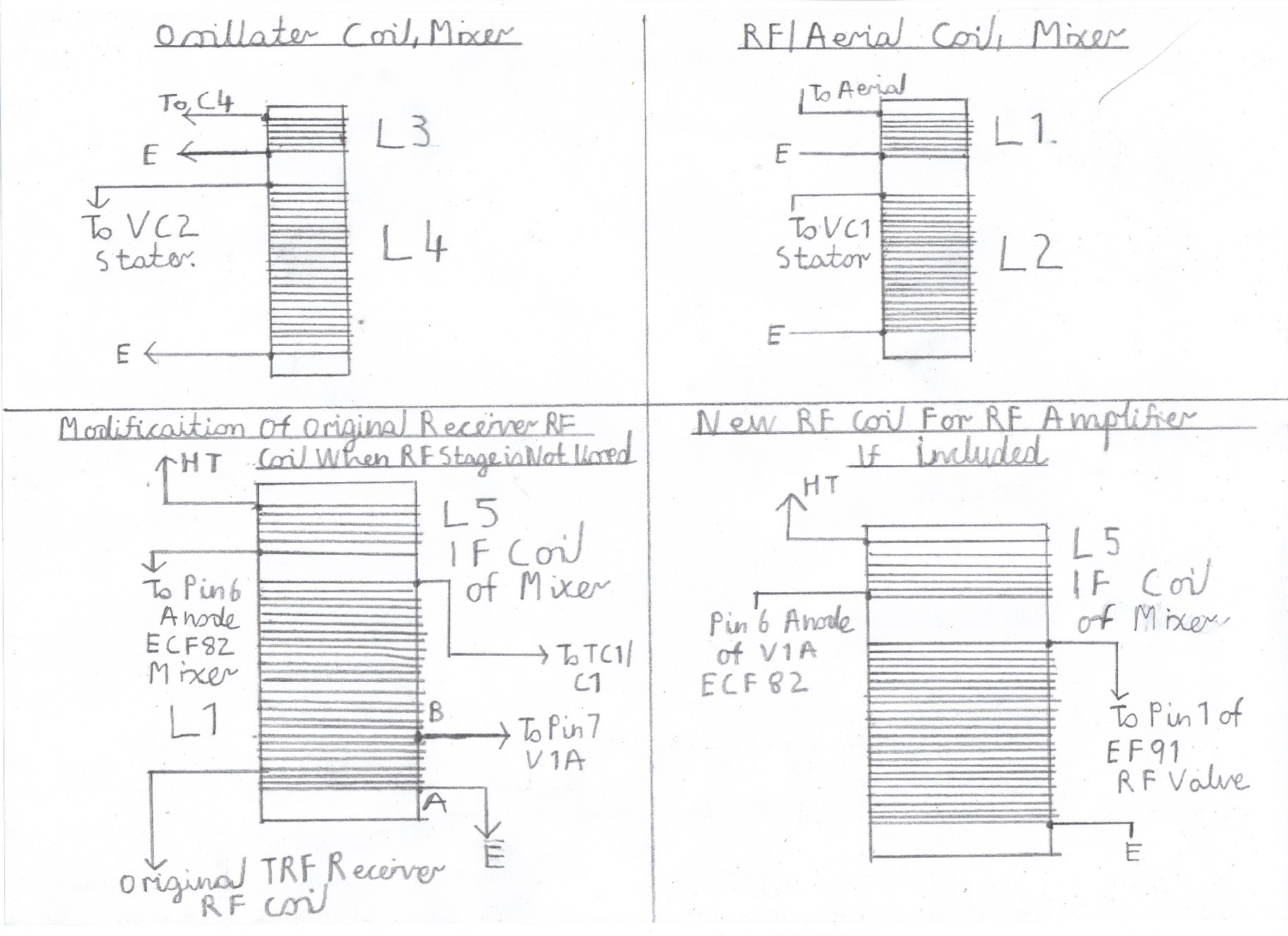
Construction of the RF Coils for a superhet receiver is more tricky then for a straight TRF Receiver, Particularly medium and long wave coils and for this reason I have not included them. Although not impossible, The performance I experienced using the old Denco Plug in type coils was very poor with severe whistling and IF Breakthrough, Particularly on the high end of the medium waves during the evening. Picture 5 refers to the physical construction of the coils and the tables below show the winding instructions for each individual band. The coil formers are 1 inch in diameter for the suggested band coverage listed in the tables below. The 15mm Coil Formers used in the TRF receiver would be OK, Although there will be slightly extended high frequency coverage.
SW1 2-5 MHZ 26 SWG
L1 10 turns.
L2/ L3 50 Turns.
L4 15 Turns.
SW2 4-10 MHZ 26SWG Recommended Coil, To get the set up and running
L1 8 Turns.
L2/ L3 24 Turns.
L4 10 Turns.
SW3 8-20 MHZ 20SWG
L1 5 Turns.
L2/3 12 Turns.
L4 6 Turns.
SW4 16-35 MHZ 20SWG
L1 2 Turns
L2/3 5 Turns
L4 3 Turns
Testing And Setting Up This Receiver
Before reconnecting the receiver, Very carefully check the wiring for any simple mistakes, Such as short circuits, wrong connections and dry solder joints. Reconnect the receiver and allow about 1 minute for all the valves to warm up. Connect to the L1 Aerial terminal about 5 metres of wire. Try rocking VC2, The oscillator and main tuning capacitor around midway to the high frequency end of the band and you should be able to tune a few stations. If this is so try rocking VC1 The mixer and aerial trimmer for maximum signal strength. If all is well it is now time to align the frequency coverage. This can be done with the aid of a broadcast receiver tuned to the frequency you are looking for, By listening for identical signals but takes longer. Connect a RF signal generator to the L1 Aerial terminal. Using tone modulation, Tune the signal generator around the range of about 4 to 10MHZ and when you hear a tone, Make a note of the frequency. If the frequency for example is about 7 MHZ, Tune VC2, Very slowly to the low frequency end of the band and keep retuning the signal generator, Maintaining VC2 for maximum signal strength at the same time. When you get to the extreme limit of the low frequency end of the band, That is with the capacitor vanes fully open, Make a note of the Frequency. If for example the frequency is now 5MHZ, This needs to be corrected. Retune the signal generator to 4MHZ and adjust the oscillator trimmer very slowly until you hear a tone. Now peak the mixer capacitor, VC2 for maximum signal strength. Repeat this step several times by doing the same procedure at both the high and low frequency end of the band, As one adjustment affects the other.
Using The Receiver
More information to follow later
Links To My Other Related HF Shortwave And Medium Wave Receiver Projects
Simple 2 Valve Regenerative Receiver
Severn Valve HF Superhet Receiver Designed For Advanced Constructors
Solid State AM/FM Pulse Counting Receiver
Simple (ATU) Antenna Tuning Unit For All HF Receiver Projects
Site Map Of All My Webpages And Favourite Valve Radio Related Links