Double Conversion Pulse Counting FM Superhet Receiver With 10.7 MHz First IF Stage
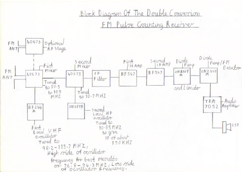
Welcome to this part of my site with a updated version of my present Transistor Pulse Counting FM Receiver . It is a slightly more advanced design with a first intermittent frequency of 10.7 MHZ, converted down to the low IF of around 150 KHZ to give better image response and elimination of second channel interference from high power local stations. Some of you may ask, what is a double conversion superhet receiver? A superhet receiver whether shortwave or FM does not have to be a single conversion relying on just one tuned oscillator and mixer for frequency conversion and many high performance communications receivers use this method. Also many short wave enthusiasts build VHF converters to plug in to the Aerial socket of a shortwave receiver to enable it to receive the the 2 metre armature band. Again this is also called double conversion and the same goes for digital TV set top boxes to convert the old UHF TV frequencies to the new digital channels. Below is a block diagram of this design which I will explain in detail. Starting from the top left of the picture is the optional RF amplifier and its purpose is to help reduce oscillator radiation and give a worthwhile improvement in RF gain, resulting in better selectivity and allows the set to use a very short antenna. Following on from the RF amplifier as you look below to the middle left is the first mixer used to convert the VHF frequency to 10.7 MHZ. The first mixer is tuned between 87.5 to 105 MHZ and in the case of this design it is broadly tuned to about the centre of the FM band. To allow the conversion to 10.7 MHZ to take place we need the first local oscillator which is pictured below the first mixer as shown in the block diagram. It is simply injected into the first mixer and it must be tuned to 10.7 MHZ above or below the FM listening frequency in question. In this design we are tuning above the FM frequency so the oscillator must tune between 98.2 MHZ to 115.7 MHZ for the conversion down to 10.7 MHZ to take place. Following on from the first mixer is the stage we call the second mixer and this is used to convert the 10.7 MHZ frequency to 150 KHZ before coupling it to the low frequency IF amplifier. The second mixer is basically tuned to a fixed frequency of 10.7 MHZ and to allow the second conversion to take place we need the second local oscillator, pictured below the second mixer tuned to a fixed frequency of 10.85 MHZ. This is what we call double conversion and before this stage can follow the IF amplifier we need the IF filter which is pictured to the right of the second mixer. Its purpose is to reject the HF megacycle frequencies and only amplify the wanted ones and is basically a simple resistance, capacitive network. Following on from the IF filter towards the middle right of the diagram is the two IF amplifier stages that follow each other. As this is a now a low frequency of about 150 KHZ they can be just simply resistive, capacitive coupled amplifiers resulting in no coils or tuning to do. The purpose of the IF amplifier is to increase the signal strength to a suitable level so it is capable of driving the FM Demodulator. Following on from the The IF amplifier, the next two stages form the FM Demodulator. It is simply an amplified voltage doubler detector known as a diode pump that converts the signal pulses into a clipped waveform which we call frequency to voltage conversion so the signal can be capable of driving the audio amplifier. Following on from the FM Demodulator is the audio amplifier pictured below on the right of the block diagram and as we all know is to make the signal big enough to drive a loudspeaker. Because this receiver configuration is a bit more complicated then my present Transistor Pulse Counting FM Receiver it is not recommended for absolute beginners to construct as a first time superhet receiver. As you are dealing with VHF, the wiring in these circuits must be short and as direct as possible with no double earths. It is also advisable to have a signal generator capable of a range not lower then at least 120 MHZ . This is because this design due to the double conversion approach is more difficult to align and needs considerable patients. If this receiver is built and aligned properly, it is capable of excellent performance and it is just as sensitive and gives the same output quality as my other design. Incidentally this type of VHF receiver does not have to be restricted to the FM Band. It has in the stages of construction been tested on the 4 metre 70 MHZ amateur band and the 2 metre amateur band with good signal strength from the Hull repeater 60 miles east of my home town of Harrogate. It can also be used as airband monitor for aircraft enthusiasts and it is a matter of just experimenting with different sized coils. Please note that details of a valve version of this receiver is now available at the following link Valve Version Of The 10.7 MHZ Double Conversion VHF/FM Pulse Counting Tuner and its performance is so good, It needs too be seen to be believed.
Block Diagram of My Double Conversion Pulse Counting FM Receiver
Construction Details Of This Receiver
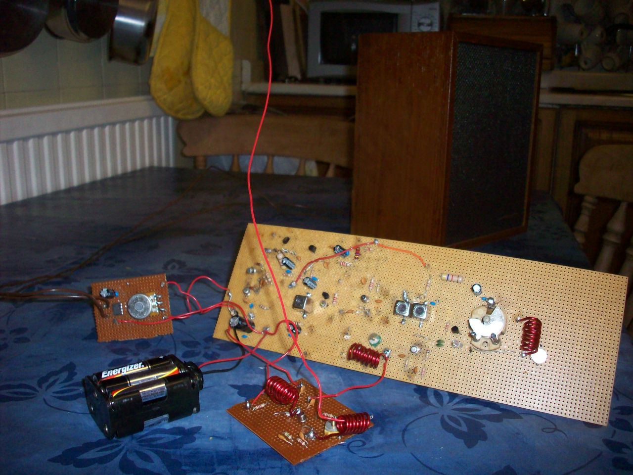
Please refer to the pictures below regarding circuit information and construction details for this receiver
|
|
|
|
|
|
|
|
|
|
|
|
|
|
|
|
|
|||
Please left click on selected picture to enlarge image.
Step 1 of the building procedure
Please make sure you have all the listed components available to hand before attempting to construct this design by visiting the following link Components List Of Double Conversion FM Superhet Receiver as some are not easily available and you may have to seek suitable alternatives such as the transistors and 10.7 MHZ IF transformers
Step 2 Special Precautions when building this receiver
Although transistors pose no shock hazard there are a several cautions that must be observed. The alkaline Duracell batteries recommended for this design must be treated with care. For instance do not allow a continues short circuit current flow between the positive + and negative - terminals to occur or the risk of leakage and explosion is very high. I would therefore strongly recommend Dry batteries such as the Eveready PP9 type when you are first connecting and testing the stages. A regulated power supply of not more then 10 volts incorporated with a current limiter is also suitable. Transistors and Integrated circuits are nowhere near as electrically rugged like valves so other precautions must be born in mind. The FET Transistors used in the mixer and oscillator need the greatest of care while handling due to damage from static. A antistatic bench mat and a whist strap connected to earth is highly recommended and also try not to handle the devices by there leads. A plastic pair of miniture tweezers is also recommended when guiding there leads into the circuit board and try to limit the soldering time to not more then 5 seconds while soldering. It is highly recommended to solder the field effect transistors last in the circuit concerned for the same reason. Transistors and electrolytic capacitors do not like wrong polarity, so you must observe the battery polarity very carefully switching on and testing . Also on the subject of battery polarity, PP3 battery clips are the worst hazard of wrong polarity particularly if you have not switched off the circuit to start with when changing the batteries and many battery operated electronic toys are damaged that way leaving children very dismayed, so it is best to get into the habit of switching off when not in use, especially when working on the circuit concerned. Also you must make sure you follow the correct component orientation of the wiring diagram very carefully regarding the transistors, electrolytic capacitors and ICs or the same circumstances may occur. If you are confident you have followed all these precautions carefully you can now go ahead with the first start of the building procedure. Please refer to step 4.
Step 3 Issues concerning stereo reception
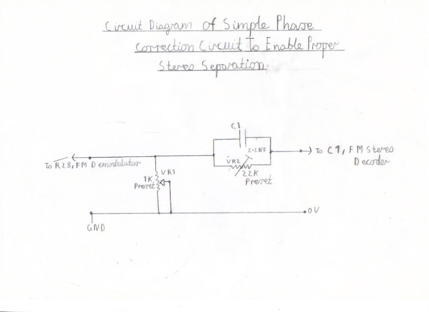
Although this type of FM Tuner is capable of superb HI FI mono quality I have only recently found out that this design is also stereo compatible. Please bear the following note before proceeding. The receiver itself does not require any modification but you need at least a very good outdoor aerial system as stereo signals need a lot more signal strength, preferably not less then 60db for this design or you will find background hiss and birdies leading to signal distortion a very big problem, noticeable more when listening to Radio Three and Classic FM. Please also note that any stereo decoder should be suitable but needs a special attenuator and phase correction circuit followed by a preamplifier in order for this design to give reliable stereo separation. A special decoder circuit for this tuner with all these facilities can be found by clicking on the following link FM Stereo Decoder Circuit . You will also need two audio amplifiers and preferably a separate power supply for powering both the decoder and stereo amplifier to ensure stability. Picture 16 features a simple phase correction circuit and this must be included before connecting the new Stereo decoder circuit. The idea of this circuit is as follows. The preset potentiometer VR1 attenuates the output circuit from the FM Demodulator and also increases the bandwidth to give much improved frequency response to enable the successful decoding of stereo signals. VR2 and the 2.2 NF capacitor follows the multiplex input of the decoder to advance the stereo signals in phase, delaying the 19 KHZ pilot tone and gives a worthwhile improvement of 30db stereo separation.
Step 4 Constructing and testing the audio amplifier
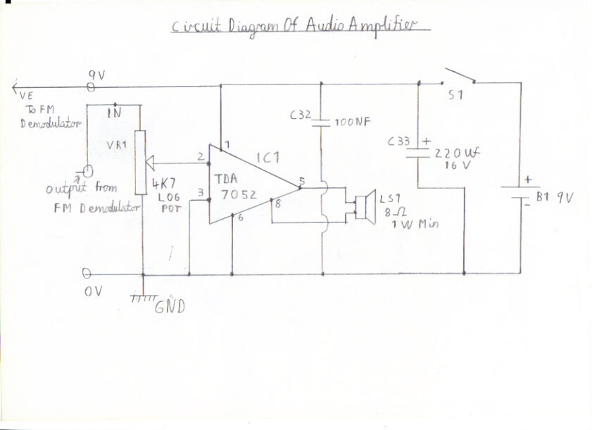
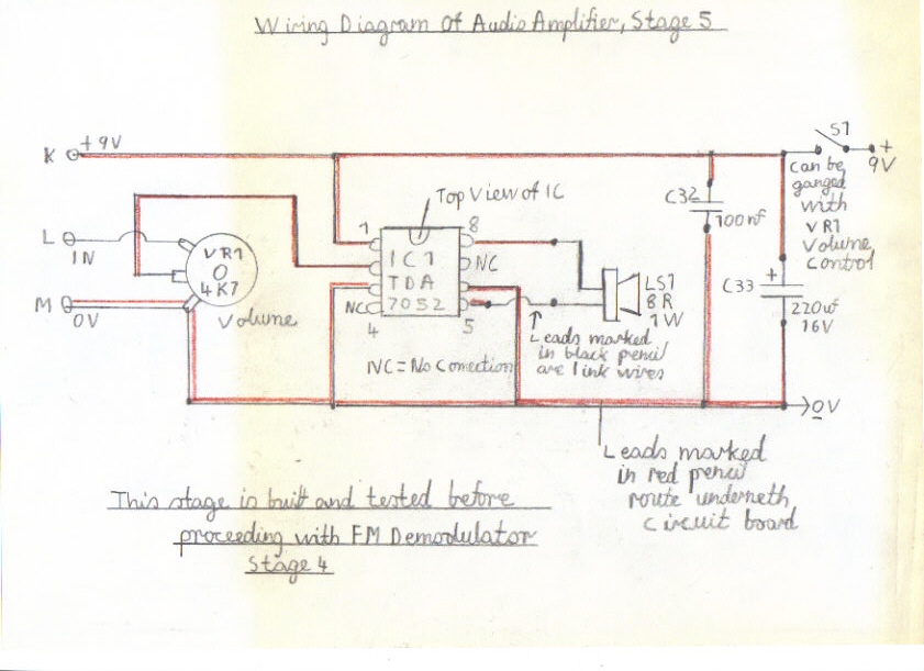
Please refer to pictures 1 and 2 for construction details of the audio amplifier. It is based on the popular TDA7052 series of audio ICs and requires only a couple of decoupling components and a volume control to get it working. It is also a lot more stable then the LM386 used in my single conversion design and is capable of about 1 Watts of audio power. Also because of its stability, the receiver can also be powered off the same 9V battery supply, saving you the cost in batteries. Picture 2 is the wiring diagram and layout for this amplifier and can be constructed on plain Vero board. Please insure that you follow the diagram very carefully regarding the component orientation. Pay particular attention to C32 the electrolytic capacitor, ensuring that the lead marked with the +Plus sign corresponds as shown in the wiring diagram. IC 1 must be mounted into a 8 pin IC socket rather then soldering it to the board and when inserting this component please make sure that the half moon shaped mould at the top of this component corresponds with pins 1 and 8 as shown in the wiring diagram. Also the leads marked in red pencil relating to the wiring diagram route underneath the circuit board. The leads marked in black pencil are link wires and must route over the top of the circuit board. The same also applies to all circuits that follow this stage. If you have wired this stage and are confidently sure you have checked the wiring and polarity of components carefully you may now proceed with testing. Start by connecting a speaker to pins 5 and 8 preferably one with not less then 1 Watts handling power. NB Smaller speakers such as the 250 milliwatt type used in miniature radios are not recommended for this amplifier. Advance the volume control VR1 fully clockwise. Connect a battery supply of 9 Volts observing the correct polarity. You will find there is no switch on clicks or soft hissing when first connecting this amplifier compared to the LM386. If you touch the Input terminal marked L on the volume control, you should hear a humming noise which means this stage is working correctly. If this is so, switch off and remove the batteries. Please refer to step 5 for construction of the FM Demodulator.
Step 5 Constructing and testing the FM Demodulator
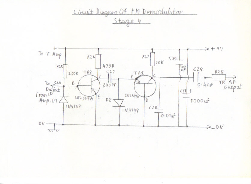
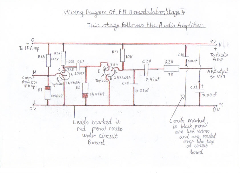
If the audio amplifier is working ok, you can now go ahead with the construction of the FM Demodulator. It is constructed on plain Veroboard and must follow the audio amplifier. Please refer to pictures 3 and 4 making sure you follow the component orientation in the same manner as you constructed the audio amplifier. Pay particular attention to the two IN4149 diodes D1 and D2 making sure the red mark corresponds with the correct polarity as shown on the circuit board. The two 2N2369A transistors TR8 and TR9 have a square metal fin that identifies the emitter lead and you must also make sure that these components correspond exactly as shown on the circuit board. If you are really sure you have wired this part of the construction stage correctly, you can now connect it to the audio amplifier ready for testing. As you can see, the connection points are marked in alphabetical order to make easy identification of there links to other stages. As in this stage the lead marked with a K must connect to the positive 9 Volt line on the audio amplifier. L is connected to the input side of the VR1 volume control and the connection point M must link to the 0V line. This also applies to other stages that follow. Reconnect the battery and switch on. If you touch connection point H, at the junction of D1and R25 with your finger or a 1.5 metre piece of wire you should hear some RF activity. As this stage is functioning as a untuned TRF Receiver in the long wave band you may be able to hear stations such as Radio 4 and other stations bunched together accompanied by hissing noise. If this is so, it means that this stage is working correctly and you can now go ahead with the construction of the IF amplifier
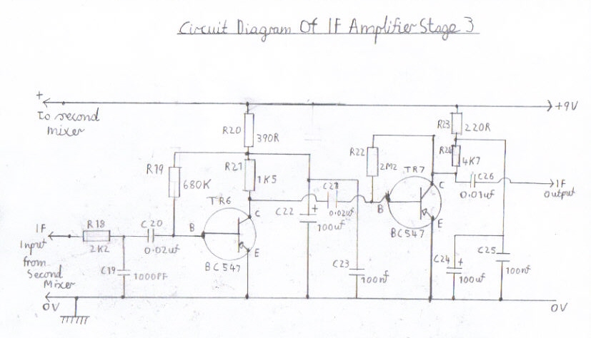
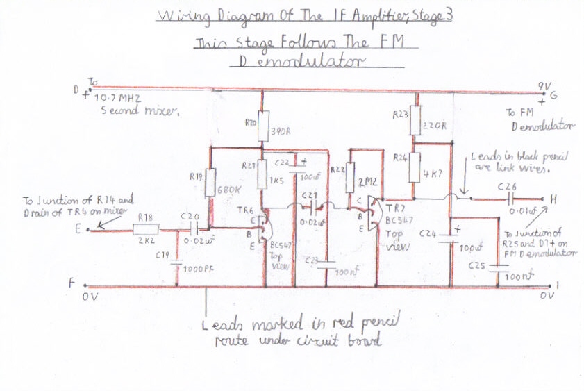
Step 6 Constructing and testing the IF Amplifier
If all has gone well with constructing and testing the FM Demodulator you may now go ahead with the construction of the IF Amplifier which will follow the FM Demodulator. As it is constructed and tested in the same way as the FM Demodulator it doesn't require much further comment. Please refer to pictures 5 and 6. The two BC547 transistors TR6 and TR7 are a half moon shape and there leads must correspond exactly as shown in the wiring diagram. If you are really sure you have wired this stage correctly you can now go ahead with testing it. First make sure you have switched off and disconnected the batteries to the other circuits before proceeding. start by linking connection point G to the 9 Volt positive line on the FM Demodulator. You now need to connect point H, which is the IF output from C 26 to the junction of R25 and D1 on the FM Demodulator. finally connect point I to the 0V line of the FM Demodulator. Reconnect and switch on. By touching point E that connects to R18 at the input of the IF amplifier, you should hear some similar activity to when you where testing the FM Demodulator, but with much louder signs of life which means this stage is working. If this is true, you may now go ahead with the 10.7 MHZ second mixer and oscillator stages which requires considerable care. NB There has been a slight error in both the circuit diagram and wiring diagram. R19 must connect to the junction of R20 and R21 rather then to the positive 9 Volt line. Pictures 5 and 6 have now been corrected and replaced.
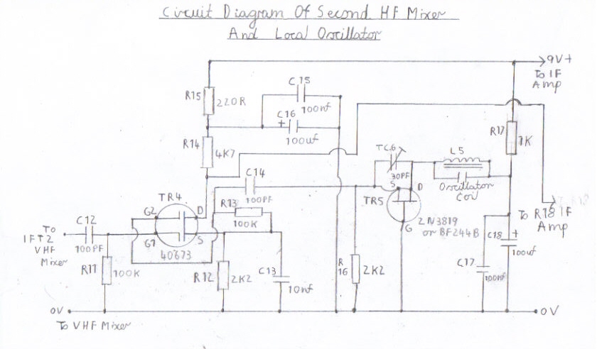
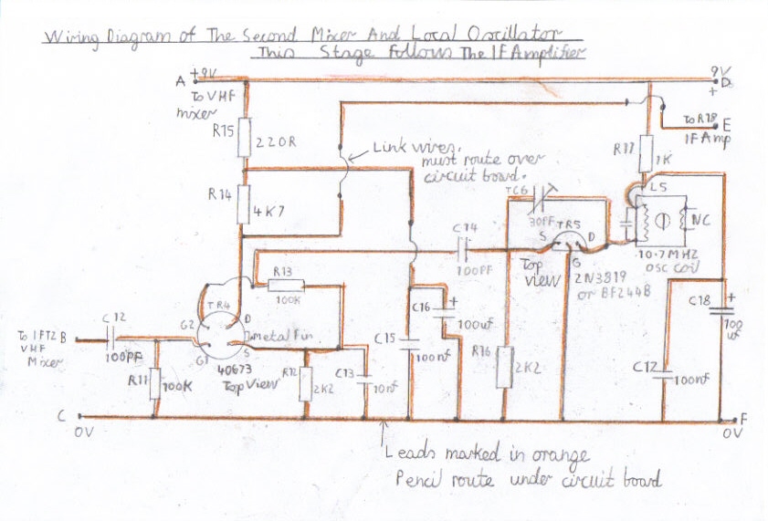
Step 7 Constructing the 10.7 MHZ second mixer and oscillator
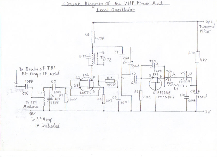
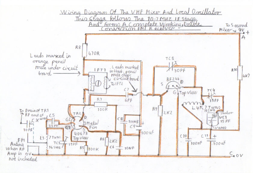
If all has gone well with the testing of the IF amplifier, you may now go ahead with constructing the 10.7 MHZ second mixer and oscillator. Please refer to picture 7 for the circuit diagram and picture 8 for the wiring diagram. Please note that a slight modification has been made concerning the mixer injection capacitor C14. The value should be 1000PF, not 100PF as shown in the circuit diagram. A correction has been rectified in the Components List Of Double Conversion FM Superhet Receiver for this item. As this stage works at a shortwave frequency of 10.7 MHZ, great care must be taken in the construction stage. Make sure that you wire this stage, exactly as shown in the wiring diagram keeping all RF leads short as possible to the IF transformers and oscillator coils. The metal can of the IF transformers and oscillator coils must also be earthed, directly to the 0V line of each circuit concerned to prevent IF radiation and detuning effects. The field effect transistors must also be handled with great care using the usual antistatic precautions I have previously mentioned. The TR4 40673 mixer transistor has a metal fin which identifies its correct polarity and must be inserted as shown in the wiring diagram. The BF244 and 2N3819 oscillator transistor are a half moon shape and also must be inserted in the same manner as I have previously mentioned. The same also applies to the VHF and RF stages that will later follow this circuit in step 9 and 12. Please proceed to step 8 for testing and aligning this stage.
Step 8 Testing and aligning the second mixer and oscillator stage
1. Please make sure you have the following tools available.
2. You need a nylon RF trimming tool rather then a screwdriver as there is risk of damaging the ferrite cores of the IF and oscillator coils. Also screwdrivers will cause detuning of the IF circuits when these tools are removed, due to magnetic effects preventing proper alignment.
3. Although experienced constructors can align this type of receiver by ear, an RF signal generator capable of a range of no less then 120 MHZ is preferable for aligning the later VHF circuits.
4. Connect the 9V positive line at point D from the second mixer to the positive line of the IF amplifier also marked as point D.
5. Connect from point E of the second mixer which is the junction of TR 4 drain and R14 to point E on the IF amplifier at R18.
6. Connect the 0V line, point F to the IF amplifier.
7. There is no really way of knowing this stage is working properly until the IF stage is connected.
8. Please refer to pictures 9 and 10, the circuit and wiring diagram before proceeding.
9. As field effect transistors are high impedance devices IFT 1 and 2 have to be wired with there low impedance windings back to back for maximum signal transfer. Like with valve circuits it is not possible to use single units.
10. The tuned winding on these transformers are identified as having 3 connections on one side and the centre tap is ignored. The low impedance coupling winding has 2 connections on the other side and it is this side that is coupled to IFT 2.
11. Connect one side of the tuned winding of IFT 2 to point B of the second mixer at C12.
12. Connect the other side of the tuned winding to the 0V line of the second mixer at point C
13. Connect the metal tag of IFT 2 to 0V at the earthy side of the tuned winding.
14. Temporarily connect one side of the IFT untuned winding to 0V.
15. Connect the red RF signal generator probe to the other side of the untuned winding of IFT 2
16. Reconnect the batteries and with a bit of luck there could be signs of life.
17. Set the signal generator to tone modulation and turn on.
18. Tune the signal generator around the 8 to 13 MHZ range until you hear a modulated tone.
19. Adjust the core of IFT 2 for maximum signal strength.
20. TC6 is the oscillator feedback trimmer and may have to be readjusted if the mixer sounds unstable with excessive oscillator noise. Closing the vanes anticlockwise increases feedback so you may have to slowly open them by turning the trimmer clockwise.
21. If the above test has gone ok you need to now set the mixer frequency to 10.7 MHZ
22. Proceed by making a note of the modulated tone in the following example. If you are receiving the modulated tone on say about 11 MHZ make a note of the frequency. Advance the core of the oscillator L5 anticlockwise until the tone disappears. Retune the signal generator until the tone reappears. This time the received frequency should be lower. Readjust IFT 2 for maximum signal strength. You will need to keep repeating this until you have got this tuning correct. The reverse procedure should also be used if the frequency is lower then 10.7 MHZ. Most signal generators have a mark on the dial to make this easier. Also leave the signal generator at the same tuning setting for testing the next stage.
23. If the above test has gone to plan you now need to wire IFT 2.
24. Remove the temporary link from IFT 2 which is at present connected to 1 side of the untuned winding and the 0V line.
25. Refer back to picture 10 for the wiring diagram and wire the rest of this stage as shown in the wiring diagram.
26. temporarily connect one side of tuned winding of IFT 1 to 0V. Reconnect the red RF signal generator probe to the other side of the tuned winding of IFT 1. Reconnect the batteries and turn on the signal generator. If you can still hear the modulated tone, adjust IFT 1 for maximum signal strength. You may have to repeat these steps a few times as one adjustment effects the other.
27. If you are confident everything has gone to plan regarding this part of the setup remove the batteries and the temporary link that you had connected to 0V and the tuned winding of IFT 1.
28. Please refer to step 9 which describes the construction and setting up of the VHF mixer and local oscillator.
Step 9 Constructing the VHF mixer and local oscillator
This is where the real excitement starts and where great care must be taken in the layout making sure all RF leads and coils to the tuning capacitors are kept as short as possible. The construction is basically the same as the second mixer and local oscillator described in step 7. The precautions regarding the Field effect transistors are also the same and need no further comment. Please also stick to the original Veroboard layout for this stage and don't even think of using stripboard or the risk of poor performance and instability may result. The mixer and oscillator coils are self supporting and require about 7 turns of 16 SWG enamelled copper wire about 10 mm diameter. Bands other then FM will also work with this receiver but do be warned that the performance starts to fall off at frequencies higher then 200 MHZ. The coils are also mounted at a different angle to avoid coupling effects and there must be a spacing of no less then 2 inches. If these precautions are followed correctly and the wiring diagram as shown, this receiver should work very well and is capable of excellent performance. Please refer to step 10 for testing and aligning this stage. Picture 17 is a new local oscillator circuit for this design and we recommend new and present constructors of this receiver to use this circuit as it results in better stability. Another advantage of this later circuit also allows earthed tuning capacitors and a dual gang type can now be used.
Step 10 Testing and setting up the VHF mixer and local oscillator
1. Connect one side of the tuned primary winding of IFT 1 to the drain of the VHF mixer transistor TR2. Connect the other side of the IFT 1 to the junction with R8, C8 and C9 of the VHF mixer.
2. Connect the 9 volt positive line of the VHF mixer, point A to the positive line of the second mixer as shown in the wiring diagram.
3. Connect the 0V line of the VHF mixer, point C to the 0V line of the second mixer as shown in the wiring diagram.
4. If you are confident you have wired this part of the circuit correctly take a breath for the real excitement.
5. Connect a short aerial lead of about 1 metre centre tapped at the L3 VHF mixer coil or better still an outdoor FM antenna with the lead from its incoming feeder loosely coupled around L3.
6. Reconnect the batteries and if all has gone well you may be in for good luck.
7. Rock the VC1 tuning capacitor and you may be able to tune in a couple of stations
8. If this is so adjust TC3 for maximum signal strength.
9. If you find that after performing the above steps, signals sound weak and distorted try adjusting IFT 1 and IFT 2 for maximum signal strength.
10. If all the above steps have gone well to plan it is now time to align the tuning range
11. If you have built my previous Transistor FM Superhet Receiver or read the article, the alignment is very similar but slightly different. For example When using 30 PF for VC1 you may find you are getting double tuning points. You may for example be tuning in Radio 2 with the vanes of VC1 halfway open. If you slowly close the vanes of VC1 in the anticlockwise direction you may find you are tuning stations that are supposed to be at the top end of the FM band near 108 MHZ. If you then close the vanes further to just near the maximum point you may pick up Radio 2 again. This may seem peculiar but I will tell you the reason so we know how to correct this. For example. If you are tuning Radio 2 on 89.3 MHZ when the vanes are nearly fully closed, the oscillator frequency is now 78.6 MHZ. If you now tune to another station further up the band, say Stray FM on 97.2 MHZ you are then tuning the oscillator frequency to 86.5. In both instances you are now tuning the oscillator 10.7 MHZ below the real reception frequency. If you retune further up the band, you will pick up Radio 2 again. Although you are receiving the same reception frequency of 89.3 MHZ you have now tuned the oscillator frequency to 100 MHZ. This means you are now effectively tuning on the high side of the oscillator frequency which is 10.7 MHZ above the reception frequency and is what we want. The oscillator trimmer TC 4 can correct this problem. As TC 4 is wired in series with the VC1 tuning capacitor you can effectively increase or decrease the capacitance of VC1. In this instance we need to increase the capacitance. Start by slowly closing the vanes of TC4 and maintaining the oscillator tuning capacitor VC1 in the anticlockwise direction. When you can tune Radio 2 with the vanes of VC2 nearly closed you have then corrected the tuning range. If this is so try tuning a station on the middle part of the band, say Radio Humberside on 95.9 MHZ. Next peak the mixer trimmer TC3 for maximum signal strength. Repeat this step several times at both ends of the band and there should be a great improvement regarding signal strength. TC 5 is the oscillator feedback trimmer and may need adjustment particularly if the oscillator is dropping out when you are tuning the lower part of the FM band. This adjustment is with trail and error and other then that you should now have a high performance working FM radio. Although there is less risk of radiating nearby interference due to the higher IF frequency I still recommend you build the featured RF stage for this design as this makes a big improvement regarding RF sensitivity. Please refer to step 11 and 12 for construction and setting up details.
Step 11 Constructing the RF stage
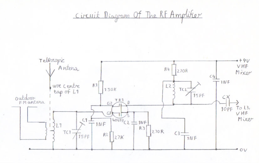
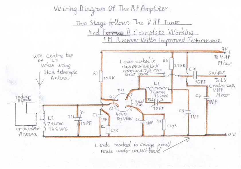
This is an optional item for this design and its purpose is to improve gain and sensitivity in weak reception areas and also has couple of advantages. As there is less likeliness of causing radiation to nearby receivers due to the local oscillator being 10.7 MHZ above the received frequency, the oscillator frequency lies within the Aircraft navigation band and it is possible if you live near an aerodrome or airport to pick up breakthrough from these transmissions. Also it allows the set to give acceptable performance from even any type of short FM antenna and is also very essential if you are going to convert this design to stereo as a more stronger signal strength is required. Please refer to pictures 13 and 14 for circuit and constructional details. The construction method and precautions are the same as for the VHF mixer and require no further comment. The RF coils must be separated in the same way as the VHF mixer at a different angle with at least 2 inches spacing from each other as shown in the wiring diagram. Special note regarding TC2. If you are using capacitive coupling to the VHF mixer like we are in this design, TC2 can be omitted. The capacitor CX is 10PF in the prototype version and this can also be replaced with a 30PF trimmer.
Step 12 Setting up and aligning the RF stage
1. Connect the 9V positive line to the positive supply line of the VHF mixer at point A.
2. Connect the 0V line to the VHF mixer at point C.
3. Connect the output from the coupling capacitor CX to ether the centre tap of L3 or the junction of L3, TC1 and G1 on the VHF mixer, whichever gives best results and might call for experimentation on various tapping points of L3.
3. Like when you tested and aligned the VHF mixer, loosely couple a short piece of 1 Metre of insulated wire around L3 or the feeder lead of a decent outdoor FM antenna.
4. Open the vanes of TC1 and TC2 near to there minimum capacitance and see if you can still tune in a few of the same stations. If this is so adjust both trimmers for maximum signal strength. Keep repeating this step by tuning through the band several times until signal strength is equal.
5. This now completes the entire construction of this receiver and I wish you all happy listening.
6. Please click on the following link YouTube - philsdoubleconversionfmreceiver1 to see a video of my prototype version of this design working.
Links To My Other FM Receiver And HI FI Projects
Transistor Pulse Counting FM Receiver
Single Conversion 6 Transistor 10.7 MHZ Pulse Counting Receiver, Designed For Stereo FM Reception
6 Valve VHF/FM Pulse Counting FM Tuner Using Safe 25Volt DC HT Line
Solid State AM/FM Pulse Counting Receiver
Valve Version Of The 10.7 MHZ Double Conversion VHF/FM Pulse Counting Tuner
3 Valve 3 Watt Stereo Amplifier
Simple Stereo Preamplifier Circuits For The 3 Valve Stereo Amplifier
Site Map Of All My Webpages And Favourite Valve Radio Related Links