Simple Radio Receiver Circuits For Beginners
This part of my site features some simple
receiver projects ranging from the simple crystal set to a working TRF
Regenerative Receiver. There are circuits available for a Solid State version of
the audio amplifier and Regenerative Receiver. Also there are valve circuits
available for constructors who prefer to use valves. All the circuits use DC
voltages between 6 to 12 volt and are absolutely safe for beginners to construct
and young children from the ages of 11 to experiment with, provided they are
under the supervision of a parent or adult regarding the safe use of batteries
and erecting outdoor antennas. We will first start off with a description of the
crystal set. Please refer the following circuit diagrams below and video clip
links, to see these receivers working before proceeding with the construction
details. The crystal receiver is the simplest and oldest receiver that has been around
on all corners of the Globe for listening to speech and music broadcasts
and people still build them today using modern electronic components. The
crystal receiver was also used for listening to England's first ever radio
station 2L2 in 1922 which due to funding in those days could only broadcast once
a week and at first it was only limited to 25 minuits airtime every Tuesday
evening. At first 2L2 only broadcast speech but as funds progressed, concerts
and music started being a more regular thing later. The power of this station
was only 100W and was limited to a 15 mile range from the transmitter location
for crystal sets and 25 miles for valve TRF Receivers such as my
Simple 2 Valve Regenerative Receiver . Back in those days and even now the crystal set can not be
strictly described as a portable receiver, despite its simplicity such as the
circuit described in picture 1. The reason for this is because it relies on a
very efficient outdoor antenna system to get the best results because there is
no RF or AF amplification and its electrical energy relies solely on the Antenna
system. In October 1922 The British Broadcasting Corporation BBC was formed and
as a result more powerful transmitters where built and reception on both crystal
and valve receivers greatly improved. Valve receivers in those days where very
expensive and the valves where limited from only 1 week to a month of there
useful life and the batteries had to be charged using a generator as many of
Britain's households did not have a public electricity supply until the early
1930s which also meant a regular trip to a garage or radio shop to add to the
expense and it was for this reason the crystal set remained popular for all
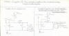
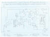
those years. The circuit described in picture 1 is simply a tuned circuit
consisting of VC1 the tuning capacitor and the tuning coil L1. The signals that
are picked up by the antenna are known as radio waves and travel at
186,000 miles per second. Heinrich Hertz the Germen Psychologist discovered
electricity and magnetism can be combined into the unit of frequency from 1
cycle per second which is referred to AC alternating current also used for the
transmission of electricity to our homes at 50 Hertz or 50 cycles per second.
The diode detector D1 is a modern germanium diode used to rectify these AC waves
into a DC direct current form so they can be recovered as audio suitable for
driving high resistance headphones or with a matching transformer, low
resistance headphones and in some cases if the signal was very good, a speaker
could be used but the volume is very limited to a quite environment due to no
amplification. The germanium diode D1 is not the original detector, a crystal
set first used but the early ones worked on the same principle as I will briefly
describe. They consisted of a rock crystal which is basically a small stone of
granite or even a small seaside pebble would surface but the performance
regarding volume would vary. A thin piece of wire that had to just touch the
crystal formed the anode and cathode and was also named as The Cats Whisker.
Resistor R1 gives forward bias for the diode to help stability and may not be
needed particularly when feeding low resistance headphones or a matching
transformer. The crystal set can be improved 1 step up by adding an amplifier to
make the audio signals bigger and the earlier form of amplification was an
electromechanical device known as the crystavox and took its power from a 6 Volt
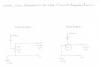
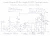
battery. Picture 5 is a suitable modern IC audio amplifier suitable for this
purpose and will also serve for amplification of the shortwave regenerative
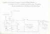
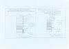
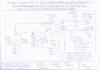
receivers described later on in this article. Picture 3 is also another simple
version of the crystal set but uses a voltage multiplier diode arrangement
similar to the pulse counting detector used in all my FM receivers featured
on this site and the performance is basically the same as the circuit of picture
1 but has a slight increase in signal strength due to the voltage doubling
action and is more recommended for constructors wishing to experiment with
loudspeaker reception. The burning question is what wavelengths and mode of
voice modulation can a crystal set receive. A crystal set can basically receive
all the HF High Frequency Radio Spectrum from 15 Metres 21 MHZ Shortwave to 1500
Metres 150KHZ Longwave. AM Amplitude modulation is commonly used as it is more
sensitive. SSB Single Side Band can not be resolved due to fact that there is no
form of oscillation in a crystal set such as regeneration or a BFO Beat
Frequency Oscillator and even if they can be picked up, they would be too weak
in anycase. The last question is can the crystal set be used for the reception
of VHF/FM transmissions. Courtney to popular belief an FM receiver does not have
to be complicated like my other designs featured elsewhere on this site but as I
said earlier on about the crystal set requiring the best antenna configuration, you need to be almost very next door to the transmitter site
and even if that, you may not get the same results regarding volume as you would
with medium or shortwave transmissions as FM needs a far more stronger signal to
resolve its carrier and slope detection must be used to recover the signal. That
is why an FM superhet receiver needs more IF intermediate stages then a MW
broadcast receiver. I will briefly describe my own experiences of trying FM
reception with a crystal Set to give you an idea of what you may be in for. Using
the simple circuit described in picture 1 I replaced the L1 tuning coil for a
VHF airspaced coil of about 10 mm diameter which consists of about 4 turns of
bare copper wire that is used for the mains earth in UK ring mains circuits. I
then padded the 350PF tuning capacitor using 10PF series trimmers to swing the
capacitance down to around a low value suitable for the VHF Range. I then linked
up my outdoor antenna system along with a straight crystal earpiece. I did at
this stage have no success in picking up anything but when I linked up the audio
amplifier described in picture 5 I could just faintly hear my local station,
Stray FM but was not very audible. This may also be because I was using the OA91
standard germanium diode which is not very good for detecting such high
frequencies within the VHF range but I have heard that the 1N34 germanium diode
works better and may be tried in the near future. An excellent website composed
by Andrew R Mitz at the following address
FM only: Low Tech FM
Radios has more information regarding the FM crystal set and also some Good
Superregenerative FM designs similar to the sets I am going feature in the later
part of this article.
|
|
|
|
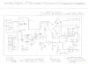
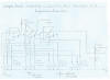
Circuit diagram of the basic crystal set. This is also the simplest radio receiver circuit you can build out of all receivers, elsewhere on this site.
|
|
|
|
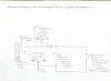
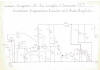
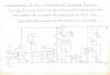
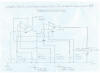
Wiring diagram of simple Crystal Receiver. Please refer to picture 7 and information text for coil construction details regarding band coverage.
|
|
|
|
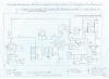
Circuit diagram of Voltage doubler crystal set. With a matching transformer you can get usable speaker volume in a quite room.
|
|
|
|
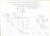
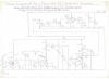
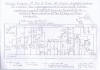
Wiring Diagram of the voltage doubler Crystal Set. This version is more recommended for driving low impedance loads such as low resistance headphones
|
|
|
|
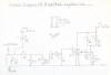
Circuit Diagram of an amplified version of the basic crystal set using an LM380 Audio IC. The amplifier will also serve for the regenerative receiver.
|
|
|
|
|
|
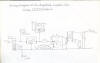
Wiring Diagram of the amplified version of the basic Crystal Receiver and is upgradable to the TRF or Regenerative Receivers featured later.
|
|
|
|
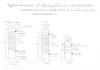
L1 Tuning Coil details for all the crystal set circuits. Woodern dowl is used to make construction very simple.
|
|
|
|
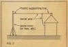
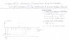
Best outdoor antenna arangement for the crystal set and for general long distance Shortwave reception with every kind of receiver configuration.
|
|

|
|
Best Earth or ground arangement for crystal receiver, mostly effective on the low frequency medium wave bands when using a short antenna.
|
|

|
|
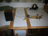
Portable medium wave crystal set using frame antenna consisting of 20 turns of 26 SWG wire wound around a plastic container.
|
|
|
|

|
|
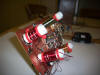
Short Wave version of the portable crystal set using about 1.5 metres of 20 SWG wire as a loop. This set works well on the 41 metre broadcast band.
|
|
|
Please left click on selected picture to enlarge image.
Please Refer To The Following Video Clip Links
To See These Receivers Working
YouTube - My Experimental Loudspeaker MW Crystal Radio.MP4
YouTube - My Shortwave Version Of The Loudspeaker Crystal Set
Working On The 41 Metre Band.MP4
YouTube - My Amplified Multiband Crystal Set Driving An LM380
Audio IC Amp.MP4
Safety Guidelines Regarding The Erection Of
Outdoor Antennas And Earth Connections
The crystal set is the simplest and safest radio
receiver to build as it needs no electric current other then an efficient
antenna preferably outdoors and in fact anyone with no
previous electronic knowledge can build one within an hour. Having said that,
there are 3 simple safety rules that do exist and that involves the safe
erection of the outdoor antennas. please refer to the following guidelines below
and then your experience of listening to free power radio should give you many
happy hours of enjoyment.
1. Picture 8 is the best outdoor antenna
arrangement and its support can be a high tree or a 20 foot mast. Insulated
tinned copper wire is the best to go for and must be strong enough to withstand
the worst of weather conditions such as the heavy wintery gales we mostly get in
these typical European Countries. Do not use the bear stranded copper wire that you
get with these so called shortwave antenna kits as due to progressive corrosion
they lose there efficiency within a week and this was in fact a weekend household task in the early days of crystal radio listening which consisted of
lowering the antenna wire supported by a pulley and cleaning off the corrosion
with steel wool. Also the use of porcelain insulators for the support wire are
available from a DIY shop will make your outdoor antenna system most effective
as the signal will not be shorted to ground during damp or wet conditions. If
you are still lucky enough to own the old GPO telephones with the analogue dial
then the dial stop will make the best antenna you could possibly go for as it is
connected to at least 1 conductor of the main BT line, providing it does not
interfere with you or any of the household who may need to use the phone.
2. A very important safety rule that must always
be obeyed at all times and that is overhead electric pylons. If you live in the
countryside such as in a rural farmhouse then the chances are that 11000 Volt
power lines normally accompanied with a 240 Volt step-down transformer exist. If
this is the case and these pylons happen to run through your back garden then
erecting an antenna could result in very dangerous circumstances. The least that
can happen if your antenna wire comes within contact with an electric pylon is
you could be badly burned or electrocuted and worst of all you and your home
could end up being a pile of ashes and it will happen so quickly it will be too
late to even know anything about it.
3. Another important safety rule that must be
obeyed when necessary is Thunderstorms which exist mainly after a long hot
summer spell. You must refrain from using your outdoor antenna system at all
times when these sort of weather conditions exist as this can result in similar
circumstances such as mentioned in rule 2 if your antenna system happens to be struck
by lightning. You must immediately disconnect your antenna and put it well out
of reach when these conditions exist and carefully explain to your child in a
firm but nice way to why he must not use the crystal set when there are
thunderstorms present or forecast.
Issues Regarding Earth Or Ground Connection
The crystal set also relies on a decent earth connection but
only on the medium and longwave bands. As you get into the real shortwave bands
around 6 MHZ 49 Metres the earth connection becomes less effective but a short
wire of about 10 metres connected to the earth and strung around a room can
improve reception as this acts as a double dipole antenna. Picture 9 is the best
outdoor earth arrangement which consists of a copper pipe about 1 metres long
driven into the ground. The connection must also be cleaned periodically
normally after a wet or heavy cold spell as the connection will lose its
conductivity due to corrosion. There is 1 more important safety rule regarding
the use of alternative earths within the home which I will briefly describe.
4. The use of a water or central heating pipe is the next
alternative if installing an outdoor earth is too much of a pain but never a gas
pipe or the earth of the mains electric wiring system within the home for the
following reasons.
5. Courtney to popular belief a gas pipe is not dangerous
provided the pipe is not accidently damaged when installing the earth connection
but your local gas company may not approve of it and may ask you to remove it or
worst of all they could take legal action against you for tampering with there
apparatus.
6. Never be tempted to use the earth of the electric ring
mains which involves strapping the earth connection to the metal case of an
electrical appliance or using the earth prong of a mains plug. The obvious
reasons for this is because the mains wiring within the appliance could be
faulty and a severe electric shock hazard may exist. Also the later idea of
using a mains plug is more dangerous because it may fall into the wrong hands of
somebody modifying the connection to the L live terminal which could result in a
fatal electric shock.
7. On a closing note, If the above simple rules are always
followed, crystal set building will provide you with many happy hours of fun and
the joy of listening to a radio broadcast many thousands of miles away from you
without the use of electric current of any kind can be a real fantasy dream.
Construction Details Of The Crystal Receiver
If you have read all the above details concerning
the antenna erection details you can now go ahead with the crystal receiver of
your choice. Please note that unless you live in a good reception area such as
open countryside the crystal set will give very poor results or not work at all
so consider erecting a decent antenna system before going ahead with the
construction of your set. Even if you outgrow from using the crystal set, the
antenna will serve for long distance shortwave reception with any regenerative
or superhet receiver that you may intend to build later on. Just a brief note
regarding the pictures of the 2 portable loop antenna versions of the crystal
receivers featured in pictures 10 and 11. The Medium Wave version will work with
quite acceptable results if you happen to live very close to a local MW station
but not as good as the versions using the long wire antenna method. The
Shortwave version has mixed results. It will either not work at all or if band
conditions are very good stations can come in very loud and it is possible in a
quite environment to even use a speaker provided a matching low impedance
transformer is used. The straight single diode detector crystal set described in
picture 1 is the easiest one and is more recommended for the absolute beginner
to build before moving on to an advanced design. Please note that the crystal
set project can be very experimental and even if you wire it up wrong there is
no danger of damaged components as there is no electric current of any kind
involved. Also as there is no regeneration or amplification involved other then
the energy from the antenna, no instability such as oscillation can exist
until you decide to add a regenerative detector. Please refer to the details
below regarding general construction details.
General Construction Details
Even if you have never had experience with
soldering before you can use techniques such as breadboard and wire wrapping and
surprisingly quite complex receivers can be made using this technique. As an
example I started my own experience using cupped screws on a base board back in
1972 during my early childhood days from the Lady Bird Book, Making a transistor
radio and the article can be found at the following link
TRF Radios 2, HAC
Radio, Ladybird Radio, Denco Green Coils . This site also has some
regenerative circuits similar to the the designs that I am going to feature
later on in this article. Soldering is obviously the best method and all your
receiver projects weather transistor or valve will work more stable due to more
secure and rigid connections. Young children must be supervised at all times
when using a soldering iron. The low voltage heat controlled soldering iron with
an isolation transformer is best regarding safety when young children are
experimenting and it must have a minimum temperature of 25W. A suitable bench or old table can be used. Also
lead Free solder is more hygienic but unfortunately does not give as good
quality shiny soldering joints as the basic resin core solder. A protective mask designed for this
particular purpose is advisable. For anyone who has never had experience of
soldering before then you must visit the following 2 links
EPE "Basic Soldering
Guide" and EPE
Basic Soldering Guide Photo Gallery as these 2 sites have all the necessary
tuition guides to the wrong and right ways if you wish to learn how to solder.
Construction Of The Tuning Coils
Please refer to picture 7 for full construction
details of all the shortwave and medium wave coils that have been found to
perform well with any version of the crystal receivers featured. Also they can
be easily modified for use with the regenerative circuits although an extra
reaction and preferably an aerial winding for better selectivity will be
required. The medium wave coil 550KHZ to 1600KHZ is wound on a 80mm X 20mm
diameter wooden dowel former and consists of 100 or 120 turns of 36 SWG of
enamelled copper wire wound side by side. Double sided Vero pins or small tack
nail pins can be used to support each terminal. Each end of the enamel must be
scraped clean before wrapping the wires around the pins and then they can be
tinned with solder to ensure good connectivity. The SW1 1.5MHZ to 4.5 MHZ coil
is wound in the same way but is wound on a 70 X 20mm wooden dowel and consists
of 55 turns of 26 SWG enamelled copper wire. This coil covers the top end of the
medium wave band and the 2 tropical short wave bands 120 metres 2.3MHZ to
2.498MHZ at the low frequency end of the range. 75 metres 3.95MHZ to 4.0 MHZ is
also possible at the high frequency end of the band. This particular coil is not
the best choice for crystal sets as these stations are low powered but when DX
condition are favourable such as late winter afternoons to early evenings, it is
possible to get some quite interesting results from these frequencies. SW2 is
the best choice of all as it covers 7.5MHZ to 15.0MHZ. It also includes the 41
metre and 31 metre Broadcast bands which are very active during the late
evenings and is the easiest coil to wind. The SW2 coil is also wound in the same
way as the other coils and is wound on a 35mm X 20mm wooden dowel and consists
of 8 turns of 20 SWG enamelled copper wire wound side by side. It is also
possible to cover the higher frequency end of the shortwave spectrum that is 16
metres 17.55 to 11 metres 26.1 MHZ but the sensitivity will be to low and that
is archived by taking around 3 turns off the SW2 coil.
Construction Of The Basic Crystal Receiver
1. Please make sure you have all the necessary to hand before
constructing the receiver of your choice by clicking on the following link
Components List Of The Crystal
Radio before proceeding.
2. Please refer to picture 1 the circuit diagram and picture 2
the wiring diagram if this is the particular receiver you intend to build. This
version is more recommended for a first time receiver. If you wish to build the
voltage doubler version of the crystal set then you need to refer to picture 3
for the circuit diagram and picture 4 for the wiring diagram.
3. If building the the receiver on plain Vero board the leads
marked in orange pencil route over the circuit board.
4. Do take special care when soldering the germanium diodes in
all versions of the receiver insuring that you don't apply too much heat. The
polarity of D1 is not important when used as a straight crystal set but if you
intend to link it to an audio amplifier later on, you must make sure the red +
positive end corresponds correctly or the sensitivity may be reduced if using an
alternative amplifier for the amplified version of the crystal receiver featured
in picture 5. If you are using the Voltage doubler version of the crystal set
featured in pictures 3 and 4 then the polarity of the diodes is very important
or the voltage doubling action will not function and the receiver may have very
low sensitivity or not work at all.
5. When using a crystal earpiece or high resistance headphones
the audio matching transformer is not required and same applies when linking the
crystal set to an audio amplifier unless the input is a low impedance input
designed for magnetic phonograph pickups.
6. If using the low impedance type of 8R earpiece that is
designed for use with transistor radios or the Sony walkman type headphones then
the T1 Audio Transformer has to be used or the volume will be very low no matter
how high the signal level entering the antenna is.
Special Issue Regarding Loudspeaker Reception
When environmental conditions are quite such as in the early
hours of the morning and providing you have a very good antenna system, it is
possible to archive loudspeaker volume with a crystal set but please note the
following. As there is no amplification, don't expect to have a free all dancing
radio that can be used at a party or when a family of say four people are
present in the kitchen having a meal. The matching transformer will be essential
as all speakers are 8 or 16 ohm specification and the larger the speaker, the
louder the volume will be. The volume is also only usable on the very powerful
stations.
Testing And Operating Your Crystal Receiver
Operating the crystal receiver is very simple and as there is
no on/off switch to worry about it may be already working almost the moment a
decent antenna is connected along with some suitable headphones.
1. Connect a suitable antenna to the SK1 Antenna terminal if
using a short antenna.
2. Connect a suitable earth or ground to the SK3 Earth
terminal.
3. Connect a suitable pair of high impedance headphones or the
specialised matching transformer if you intend using low impedance phones or a
loudspeaker.
4. Now for the moment of truth. By rotating VC1 it may be
possible to at least tune in 2 or more high power stations within your region.
5. If the high power stations are untunable, then your antenna
is too long and you need to swap over to the SK2 antenna socket which is
connected in series with the antenna tuner VC2.
6. Closing the vanes of VC2 highers the capacity of VC2 which
needs to be at this setting when signals are weak.
7. Opening the vanes of VC2 lowers the capacitance and will
help separate the strong signals by attenuating the signal and some of the
weaker ones will also be heard. Also this method will match your antenna more
efficiently although a coupling winding over the antenna coil is a better
alternative and will be used with the regenerative circuits.
7. Hope you have many happy hours of using your crystal
receiver and it should learn you a great deal on how the radio receiver works
before progressing to advanced circuits such as the audio amplifier that will be
the next step up from the crystal set.
Constructing The Audio Amplifier To Form An
Amplified Crystal Set
As the crystal set is obviously your first
working receiver and presuming you have managed to get the project working ok I
can not see why you should not progress further afield towards building this
simple IC audio amplifier which will greatly improve the volume of the crystal
set and will serve for the TRF and regenerative receiver circuits later on.
Please refer to picture 5 which is the circuit diagram and picture 6 the wiring
diagram of the amplified crystal set. The LM380N Audio IC used in this circuit
has been around since the early 70s and was used in cheep record players and
music centres of that era. It has a maximum output of about 2 Watts audio power
when used with an 18 Volt supply but as we are only using a 9V battery supply
the power will be limited to around 500mw which is more then enough volume for
this particular application. If treated with care, it is a very reliable audio
IC and also features short circuit protection and thermal shutdown to protect
this IC. Before proceeding with this circuit and that also includes the
regenerative circuits that will follow, please take the time to read these
simple precautions related to the safe use of alkaline batteries and the
polarity of certain components.
General Safety Precautions Regarding The Safe
Use Of Alkaline Batteries And Low Voltage Circuits
As these circuits use a safe low voltage of no more then 12
Volts there is no serious electric shook hazard involved but please read these
simple rules regarding the safe use of batteries and the polarity of certain
components, then hopefully you will gain further enjoyment in building these
other receiver projects. As dry cell batteries are no longer available we all
have to resort to using high power alkaline batteries. The good advantage is
they have a longer life span but the downside of them is that they are capable
of delivering more excessive currents and are not really suitable for young children to
experiment with unless supervised by an adult. Please read the following
guidelines below before proceeding with the amplifier circuit.
1. Avoid shorting the terminals of these batteries as a
continues short circuit will cause them to heat up and possibly explode which
could also be a fire hazard.
2. As we all know, solid state circuits are nowhere as rugged
as valve circuits so you must double check the polarity of certain components
and general wiring before connecting up the battery supply or permanent damage
may result.
3. You must at all times pay attention to the polarity of
electrolytic capacitors as these can heat up and explode causing there innards
to deposit all over the place. Most electrolytic capacitors have a continues
stripe marked down the can for the negative terminal and you may notice it being
a shorter lead.
4. Also as a final precaution, double check the battery
polarity and it is advisable to have a switch in the positive supply line so the
circuit can be switched off when not in use and also helps an accidental brush
with the wrong polarity when changing batteries as this can also cause permanent
damage.
General Construction Details Of The Audio
Amplifier Circuit
1. Please make sure you have all the components to hand before
attempting to construct this version of the receiver by visiting the following
link Components List Of The
Crystal Radio and refer to pictures 5 and 6 for the circuit and wiring
diagram.
2. If you are now confident you have followed all the above
procedures you may now go ahead with the basic construction of this simple
amplified crystal radio circuit. A 14 Pin DIL socket is advisable for IC 1 as
excessive heat can damage this IC when soldering. NB
There is a notch on this IC which corresponds to pins 1 and 14 which I
forgot to include in the circuit diagram and I will update it at a later stage.
If this sounds confusing, then the amplifier for my
Solid State AM/FM Pulse
Counting Receiver Designed For HF Short Wave Band Reception As Well As Superb
Clear VHF/FM Reception is exactly the same version and can be copied from
the following link
wiringdiagramoflm380naudioamplifier.jpg until I rectify this mistake.
Testing The Amplified Crystal Set
1. If you are confident that you wired everything
correctly then you may give it a first time test but it may be advisable to
double check again, particularly if this is your first time electronic project.
Make sure in particular that there are no dry solder joints or whiskers that are
a common cause of short circuits and a magnifying glass is a very handy tool for
checking these most common mistakes.
2. Connect a suitable 8 Ohm speaker to the
amplifier output and a suitable antenna to the SK1 Antenna terminal.
NB If it is a very long outdoor antenna you are
using you may have to use SK2 or receiver overload may result and the
selectivity will be very poor.
3. Connect a suitable 9 Volt supply, making sure
you observe the correct polarity and switch on for the great moment of truth.
4. If all is well, you should at least be able to
hear some sort of activity such as a soft hiss in the speaker and touching the
positive side of the D1 diode detector should produce a buzz when the VR1 volume
control is advanced.
5. By rotating the VC1 tuning capacitor, it
should be possible to tune in a few stations in the same way as the basic
crystal set but with much greater volume. Also the operation is very much the
same as the other crystal set circuits.
6. This now completes this section regarding the
crystal set project and I am pretty sure you will be wanting to move on to a
more advanced regenerative receiver project. If you have already outgrown your
crystal set then the VC1 and VC2 Tuning capacitors will serve for this along
with the LM380N audio amplifier circuit.
Simple Regenerative TRF Receiver
This section features a regenerative receiver capable of
receiving all the Medium wave to the entire HF Shortwave radio spectrum between
550 KHZ to 30 MHZ. There are 3 versions of this receiver. The first version is a
simple 1 transistor receiver that will just drive the LM380N audio amplifier
when signals are strong and is suitable for an absolute beginner to construct
who has had previous success with the crystal radio circuits. The second version
features simple band switching and a tuned or untuned RF stage can be added. The
third version features an input audio pre amplifier which will improve volume
and make weak stations more hearable. I will give you a brief description of how
the Regenerative Receiver works and its history. Any Valve or Transistor can
form as a detector for rectifying RF signals into audio in the same way as the
crystal detector by using what we call leaky grid detection or anode bend
detection and can also function as an RF Amplifier at the same time. Also more
tuned stages can be added ahead to form what we call a TRF Tuned Radio Frequency
Receiver. Although using this method can make the receiver more selective and
have more gain, It is more costly to build as each RF Stage requires an extra
tuning capacitor and unless they are all ganged together it would be a very
difficult receiver to use as each tuned circuit needs to track at the same
received frequency. This is why the later Superhetrodyne receiver eventually
gained popularity and still to this day, It is widely used for all forms of
radio communications. The great inventor Edwin Armstrong invented the
Regenerative Detector in 1914 before moving onto the invention of the now widely
used Superhetrodyne receiver which many radio technicians like myself call it
the Superhet for short. To make an RF amplifier regenerative you need to
amplify the output signal back into its input. In the most simple case it can
be done by using a capacitive method which is also used in very simple
regenerative receivers by connecting a capacitor between the anode and grid of
any Triode or Pentode valve in which we now have what we call Positive Feedback.
In early valve days it was also called Reaction but is now described in modern
terms as Regeneration and as a result you can increase the gain of an RF
amplifier by a factor of 15,000 or more. Applying too much Regeneration causes
the RF amplifier to go into oscillation and is described as a squalling noise
which can make the signal you are listening to unintelligible or cause illegal
interference to nearby receivers which are tuned to the same frequency, So we
need to find some way of bringing this situation under control in which I will
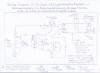
give you an example. By referring to picture 3 which is the circuit diagram of
my 1 Transistor Regenerative Receiver you need to note the following points. L1
is the main tuned circuit which is simply tuned to the frequency of interest and
is capacitive coupled to the Gate input of TR1 with R1 forming bias. L2
is what we now call the feedback or regeneration coil. The signal is now fed
back from the Drain of TR1 through the coupling capacitor C2 which also blocks
the passage of DC and only allows AC signals to pass. The signal is then coupled
to L2 which also must be inductively coupled in the correct phase which means
having the windings of L1 and L2 in the same direction of the Magnetic Field or
Regeneration will not work. The RV1 Potentiometer control is the KEY to bringing
this Regenerative Detector under control which I will briefly describe. By
rotating RV1 in the anticlockwise direction you are directing the track of RV1
in the earthy direction which also reduces the RF Radio Frequency Current to L2
resulting in less positive feedback and we now have a usable Regenerative
Receiver. The receiver is at its most sensitive when RV1 is set just before the freshhold of oscillation and you will have to maintain this control when
retuning the receiver to different frequencies which is the main disadvantage of
the regenerative receiver. Another popular method of regeneration control is to
have C2 as a variable capacitor and RV1 omitted but it is in my opinion the less
preferred method for obvious reasons. Firstly, You have the increased cost of
buying another tuning capacitor and it also results in detuning effects and
backlash. Also many constructors that have built valve versions of this receiver
have experienced burned out feedback coils and HT load resistors when using the
variable capacitor method of regeneration due to the simple fault of the
capacitor vanes shorting to each other. Despite the drawbacks of this simple
receiver, It is 1 learning stage up from the Crystal Set and you should have
many happy hours of fun, Before going on to more adventures in the world of
Wireless.
|
|
|
|
Prototype version of the complete regenerative receiver. This design incorporates band switching of the entire short wave spectrum.
|
|
|
|
Overview of the band switching arangement of the regenerative receiver. As you can see copper clad board is used, resuling in exellent stability.
|
|
|
|
Circuit diagram of the 1 transistor FET Regenerative version of the TRF Shortwave receiver with LM380 Audio Amplifier.
|
|
|
|
Wiring diagram of the 1 transistor Regenerative Receiver. Basic receiver is wired using copper cladboard and tagstrip, similar to valve circuits.
|
|
|
|
Simple band switching circuit to enable full HF coverage of the entire shortwave spectrum. Designed for the 1 transistor Regenerative Receiver.
|
|
|
|
|
|
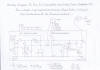
Circuit diagram of the 2 transistor FET Regenerative Receiver. This version incorporates an untuned RF stage which gives a slight increase in RF gain.
|
|
|
|
Wiring diagram of the 2 Transistor Regenerative Receiver. This is the same version as the 1 transistor design exept an untuned RF Stage is used.
|
|
|
|
Circuit diagram of the 3 transistor Regenerative Receiver. Basically the same as the 2 transistor version but includes AF preamplifier stage.
|
|
|
|
Wiring diagram of the 3 transistor Regenerative Receiver. This is the best performer regarding AF sensitivity on all bands.
|
|
|
|
Simple band switching circuit designed for the 2 and 3 transistor version of the FET Regenerative Receivers.
|
|
|
|
|
|
RF Tuning Coil details for all the Regenerative Receivers. Please refer to the text provided in the contruction article for full information.
|
|
|
|
Simple Variable Aerial Attenuator Circuit. Highly recommended for the 2 and 3 transistor Regenerative Receivers when using long wire antennas.
|
|
|
|
Simple ATU Antenna Tuning Unit. Effectively matches long and short antennas for maximum signal transfer. Suitable for all my receiver projects.
|
|
|
Please left click on selected picture to enlarge image.
Please Refer To The Following Video Clip Links
Below To See These Regenerative Receivers Working
YouTube - My Solid State FET Version Of The Regenerative Receiver
Working On MW.MP4
YouTube - My Solid State Version Of The FET Regenerative Receiver
Working On Shortwave
Construction Details Of The 1 Transistor
Version Of The Regenerative Receiver
Before commencing with the construction of these
featured Regenerative Receiver projects it is very advisable to refer to the
following link
Components List For All Versions Of The Solid State Regenerative Receiver
which will have a list of all recommended component suppliers.
Important Guidelines Regarding Safety And
General Construction Layout
As I presume you have read the safety article
Relating to the Crystal Set, The rules are exactly the same regarding the safe
use of Antennas and the polarity of certain components such as the electrolytic
capacitors and Batteries if you have built the amplified crystal set. Do pay special attention with the polarity of the FET
Field Effect Transistors. The 2N3819 FET is not as static sensitive as other
expensive MOSFET devices used in other applications such as high power PA
Amplifiers, But you must try to handle it as little as possible and try not to
apply no more then 5 seconds of heat when soldering into the circuit which
should be just enough to make a nice clean shiny joint. Veroboard is
suitable for the audio amplifier circuit, But I do strongly recommend the old
style of wiring which is the use of laminated PCB board, Because it forms an
excellent ground plain resulting in less hand capacity effects when tuning in
the higher shortwave frequencies. Also do not overlook the advantage of using
the valve style method such as aluminium cases and tag board.
General Construction Of The Receiver
Please refer to picture 3 which is the circuit
diagram and picture 4 the wiring diagram. The copper cladboard specially
recommended for all these versions of the regenerative receiver is available
from Maplin Electronics code
WF41U and should accommodate all hardware and components. The RF coils weather
band switching is used or not are best mounted on the left hand side with the
tuning capacitor in the centre. Also if band switching is used you must mount
each tuning coil about 2 inches or 40 mm apart to avoid coupling effects and
make sure that you keep wiring in the tuned circuits as short as possible,
Particularly the SW3 high frequency coil. The other wiring is not as critical
but do try to keep it as neat and short as possible. All Wiring of this receiver is supported by
tagboards and points marked E are chassis earth return points in which all leads
can solder direct to the copper board. There is one exception regarding the
LM380N audio IC Amplifier chip. It must be mounted on veroboard and a 14 pin DIL
holder is recommended to avoid the risk of damaging this IC when soldering. Also
you must make sure this IC is wired or plugged into the holder with the correct
polarity or it may be immediately destroyed. A notch and small moulded dot
at the top confirms the correct polarity. The TR1 FET Transistor must also be
wired into the circuit in the correct orientation or this component will also be
damaged. It is a half moon shape and its lead-out base is viewed at the bottom
as you can see in the wiring diagram. It is best to mount all components such as
the tuning capacitor and all other components such as controls before commencing
with the general wiring of the receiver. A soldering Iron with a minimum rating
of 25W is recommended and leaded resin core solder is recommended for clean
reliable soldering. This receiver can also be tested before connecting the
tuning coils as they are all capacitive coupled rather the forming part of the
biasing network which is the case when using source or cathode feedback which
would immediately damage the FET Transistor due to an open circuit. If you
confidently understand these procedures you can now go ahead with the
construction of this receiver. Before testing this receiver double check the
polarity of all components such as the FET Transistors, Electrolytic Capacitors
and IC1.
Testing The Receiver
1. If you are confident you have carefully gone
through all the above procedures you may now test this receiver before going
ahead with winding the RF Tuning Coils.
2. Connect a suitable 8 Ohm Speaker to the SK4
and SK5 Speaker output of about no lower then 500mw rating.
3. Connect a suitable 9 Volt power supply,
Preferably 6 AA 1.5V cells making sure you observe the correct polarity.
4. If all is well you should now hear a soft hiss
in the speaker.
5. Advance the RV2 volume control fully
clockwise.
6. By touching the Gate of TR1 or the stator
moving vanes terminal of VC1 you should now hear a loud pitched buzz. If this is
so, You have now got the receiver working correctly and it is now down to
winding the tuning coil of your choice to start enjoying short wave reception on your
first regenerative receiver project.
Winding The RF Tuning Coils
The RF tuning coils are home made in a similar
way to the crystal set and are a bit more complex because 2 extra windings are
required in addition to the main tuned circuit. 15mm diameter plastic tube is
used and is available from most DIY Stores. If you happen to be lucky and have
an old set of the Denco type plug in coils then it will save you a job with coil
winding. Please bear in mind that these coils are no longer available but as
this type of receiver can be experimental it is not that difficult as it seems
provided you follow the later instructions very carefully.
1. Please refer to picture 11 which shows you the
physical details of how these RF coils are wound.
2. You must also make sure that the tuning coil
L1 and L2 Regeneration Coil are connected in the correct phase as shown in the
diagram or regeneration will not be possible. All windings must also be in the
same direction and although the antenna coil L3 is not as critical, It still
must be connected as shown or there will be a reduction in sensitivity. Also to
save winding L3, An antenna may be connected direct to the hot end of the tuning
coil via the TC1 Trimmer capacitor although bear in mind that this is not the
best method when using long antennas unless you have lose enough capacitance as
it can be responsible for unreliable regeneration when tuning certain parts of
the band concerned and also signal overload that reduces selectivity.
2. Please refer to the information table below
for coil winding details for the band of your choice.
Medium Wave 550KHZ - 1600KHZ
L1 Tuning Coil 130 Turns
L2 Regeneration 30 Turns
L3 Antenna Coil 20 Turns.
36 SWG enamelled copper wire is used and turns
are wound side by side.
SW1 1.6 MHZ - 4.0 MHZ
L1 Tuning Coil 60 Turns
L2 Regeneration 15 Turns
L3 Antenna Coil 15 Turns.
26 SWG enamelled copper wire is used and turns
are wound side by side.
SW2 6.0 MHZ - 15 MHZ NB
Best band choice as a starter for getting the receiver up and running as
this frequency range has 24 hour European coverage
L1 Tuning Coil 13 Turns
L2 Regeneration 8 Turns
L3 Antenna Coil 4 Turns
20 SWG enamelled copper wire is used and turns
are wound side by side.
SW3 9.0 - 30.0 MHZ
L1 Tuning Coil 6 Turns
L2 Regeneration Coil 4 Turns
L3 Antenna Coil 2.5 Turns.
20 SWG enamelled copper wire is used and turns
are wound side by side.
Special Notes Regarding Bandswitching
Simple band switching is possible with this type of receiver
and is achieved by using the simple switching circuit described in picture 5.
For first time constructors to this receiver it is advisable to get it working
as a single band receiver first, To ensure all frequency band coils work
correctly and that you have gained enough experience of how the receiver works
before making modifications. You must also make sure you keep all RF wiring to
the band switch as short as possible without the insulation of each lead
touching another as this can lead to stray capacitances. One final note
regarding the subject of bandswitching. You must also make sure that the SW3
coil has the shortest route of wiring to the bandswitch and all coils must be
spaced around 40mm from each other to avoid undesired stray coupling that can
also cause a considerable reduction in performance.
Initial Testing Of This Receiver
1. Connect a short antenna of about 4 metres of insulated wire
as a start to the SK2 antenna socket.
2. Advance the TC1 Antenna trimmer vanes around mid setting.
3. Advance the RV2 Volume control clockwise to around mid to
full setting.
4. As a final note double check all wiring and reconnect the
battery, Making sure you observe the correct polarity.
5. By rotating RV1 clockwise, The set should break into
oscillation which means everything should be working OK.
6. Slowly advance RV1 anticlockwise until the oscillation just
stops.
7. By rocking the VC1 tuning control it should be possible to
tune in some station depending on the band you are tuned to regarding the time
of day and band conditions.
8. You will find that you will have to keep maintaining the
regeneration control as you tune from one end of the band to the other and you
must accept that this is normal and is the main disadvantage with the simple
regenerative receiver which is why the Superhet Broadcast Receiver became the
worldwide consumer standard during the early 1930s.
9. You may find when using SK2 as your antenna source that
regeneration can be unreliable and detuning effects occur. If this is so then
you need to reduce the capacitance of TC1 by gradually opening the vanes until
oscillation of the regenerative detector can be maintained.
10. If you have a long outdoor antenna then the SK1 antenna
socket has a big advantage. The receiver is less prone to overloading by strong
signals and the regeneration should be more reliable resulting in no dropouts
when the antenna is moved. Also the receiver should be more free from frequency
detuning effects.
11. If you find that regeneration cuts in to soon, that is
with RV1 at its lowest setting or is uncontrollable then the following tips
should help. Try removing a turn or so off L3 and this should improve matters.
Also decreasing the value of C2 may also help and having the R7 decoupling
resistor replaced with a 10K preset may also help matters.
How To Receive SSB Single Sideband And CW
Continues Wave Reception
Although a BFO Beat Frequency Oscillator is
required when receiving SSB on a Superhet Receiver, The regenerative detector is
opposite which is 1 good advantage about this type receiver that also saves the
cost of expense compared building a complex communications receiver. Most SSB
and CW Morse is listened to on the Amateur Ham HF Bands although shipping, Long
range aircraft and coastguard stations still use it and some interesting
transmissions can be picked up. Meanwhile if your interest is listening to
amateur radio then the SW1 1.6 - 4.00 is the best coil to use as this covers the
the 80 metre band 3.5 - 3.8 MHZ which is still a very popular evening chat and
long distance DX Band. The 160 Metre 1.8 - 2.0 MHZ known as Top Band can
sometimes be picked up but as this band only allows a maximum of 10 Watts of
transmitter PA output power it is not as active.
1. A sideband signal is identified by tuning in a
garbled and distorted speech when using normal AM Amplitude Modulation.
2. If this is the case you then need to resolve
this issue which involves advancing RV1 clockwise until the receiver just breaks
into oscillation.
3. By carefully and slowly rocking the VC1 Tuning
capacitor within each side of the frequency carrier you should be able to
resolve the signal in the form of Donald Duck or someone talking through a
drainpipe which is normal when using this mode of transmission.
4. Although this is quite OK to have the detector
oscillating when receiving these type of transmissions, Avoid having the
receiver in this continues state when in particular using the Medium Wave
broadcast band as this may cause interference to nearby receivers which is
classed as illegal.
Finally
I hope you have managed to build your first
working regenerative receiver successfully and this will certainly give you an
inexpensive means of listening to the world, Right at your finger tips which is
great step up from the simple Crystal Receiver. If you want to improve on the
simple 1 transistor regenerative receiver then why not try the 2 transistor
version of this receiver which includes an untuned RF stage and the 3 transistor
version includes an AF preamplifier which also gives a considerable boost in AF
gain.
Construction Details Of The 2 And 3
Transistor Version Of The Regenerative Receiver
The 2 transistor version of this receiver is
basically the same configuration as the 1 transistor version except it has 1
slight improvement. It incorporates an untuned RF Amplifier which has 3
advantages. It isolates the antenna from the regenerative detector which can
radiate illegal interference when the detector is oscillating and also
eliminates unreliable regeneration when tuning certain sections of the band due
to tight antenna coupling. It also has a slight increase in gain and sensitivity
when using short antennas. It would also be much better to have the RF amplifier
tuned, Except this would increase the complexity of the receiver requiring an
extra tuning capacitor and coil for the band concerned and would require careful
planning of the circuit layout if the risk of stray coupling and instability is
to be avoided. The construction and setting up method is the same as the 1
transistor receiver so there will be less comment other then you need to refer
to picture 6 for the circuit diagram and picture 7 for the wiring diagram. Also
if you wish to incorporate band switching then I have some very good news. It is
much easier then the 1 transistor version as there is only the tuning coil
winding and the regeneration winding to switch. If You are planning to include
band switching then you need to refer to picture 10 which has the full circuit
diagram for switching all 4 frequency ranges of the shortwave spectrum. As the
RF Stage is untuned it is strongly recommended to include the simple RF antenna
attenuator circuit in which you need to refer to picture 12 or the risk of
overload and untunable signals may make the receiver more unselective
particularly when using a long wire antenna. There is a very useful and simple
circuit that has been included which I will briefly describe. It is
an accessory that every serious SWL shortwave listener should process. It can be
used on all types of shortwave receiver including my
Severn Valve HF Superhet Receiver Designed
For Advanced Constructors except the AC/DC type where a live chassis exists,
As this could pose a serious electric shock hazard. It is called an ATU short
for Antenna Tuner Unit and it consists of a series resonant tuned circuit of a
tapped switchable coil and parallel tuning capacitor at the antenna input. The
purpose of this item is to reduce out of band signals and when tuned properly it
effectively matches the antenna which results in a more efficient signal
transfer which is responsible for a great increase in gain with less background
noise. Please refer to picture 13 if you wish to include the simple ATU circuit. The 3 transistor version of this regenerative receiver is also basically
the same as the 2 transistor version except an AF audio input preamplifier has
been included which also gives a worthwhile increase in audio gain particularly
when receiving very weak stations. If you intend building this version of the
regenerative receiver then you need to refer to picture 8 for the circuit
diagram and picture 9 for the wiring diagram. As the RF tuning coils are
slightly different regarding the text in the circuit diagrams and to avoid
confusion with the details for the 1 transistor version please refer to the coil
table below.
RF Coil Details For The 2 And 3 Transistor
Regenerative Receiver
Medium Wave 550KHZ - 1600KHZ
L1 Regeneration 30 Turns
L2 Tuning Coil 130 Turns
36 SWG enamelled copper wire is used and turns
are wound side by side.
SW1 1.6 MHZ - 4.0 MHZ
L1 Regeneration 15 Turns
L2 Tuning Coil 60 Turns
20 SWG enamelled copper wire is used and turns
are wound side by side.
SW2 6.0 - 15 MHZ
L1 Regeneration 8 Turns
L2 Tuning Coil 13 Turns
20 SWG enamelled copper wire is used and turns
are wound side by side.
SW3 9.0 - 30 MHZ
L1 Regeneration Coil 4 Turns
L2 Tuning Coil 8 Turns
20 SWG enamelled copper wire is used and turns
are wound side by side.
This now completes this article regarding the
construction of the simple solid state HF Shortwave Regenerative receiver. Many
constructors may wonder, Is it possible to use this version of the Regenerative
receiver to listen to VHF/FM broadcasts or the 2 metre Amateur Band.
Unfortunately because of its lack of sensitivity for VHF use, This type of
Regenerative Detector is not suitable but the article below features a simple 3
Transistor Super Regenerative Receiver and is convertible to a simple Superhet
Receiver using no coils pulse counting technology.
Simple VHF Receivers
This section features 2 simple VHF Receivers. The first is a
simple Superregenerative receiver which I will briefly describe its operation.
The Superregenerative detector works in a similar way to the standard
regenerative detector except it is more sensitive at working on the higher VHF
frequencies and also the most inexpensive way of producing a simple portable FM
Receiver. It is also as easy to build as the standard regenerative receiver.
Inventor, Edwin Armstrong found by using an interruption oscillating method that
is known as the quench oscillator that a signal can be amplified at supersonic
rate that is more powerful then the basic regenerative detector. Although Edwin
Armstrong was the Pioneer inventor of FM Radio Broadcasting, He did not approve
of using the Superregenerative detector for receiving FM broadcasts for obvious
reasons which I will Briefly describe. Because the detector is always
oscillating at reception frequency which can be identified by a potent
background hiss, In the absence of a strong signal they can radiate illegal
interference to other listeners unless the receiver is enclosed in a metal box
with an RF Amplifier to isolate the Antenna and it was this reason that
Armstrong himself did not want his FM service to receive bad publicity.
Superregenerative detectors also found there use in simple walke talkie
transceivers that are available as toys and model aircraft fans have used them
as an inexpensive way of getting there plains to fly but also because of there
low selectivity many people had to wait there turn if the frequency was close to
an adjacent channel or a model air pileup would result. I will briefly describe
how mine version works by simply referring to picture 1 which is the circuit
diagram. The first stage TR1 is an FET grounded gate untuned RF stage and its
purpose is to isolate the antenna from the detector to eliminate unreliable
oscillation when tuning from one end of the FM band to the other. The RF Stage
also plays its role in reducing illegal interference from the antenna which is
one of the main reasons why this receiver lost its popularity as a simple FM
receiver in the early 50s when the Ratio Detection method was introduced in the
commercial broadcast superhet receiver. The second stage TR2 is the main ingredient that
makes this receiver work. It is a self quenched Superregenerative detector
consisting of the Colpitts Oscillator also invented by Armstrong and is very
sensitive and capable of receiving the entire VHF Radio spectrum between 30 MHZ
to about 200 MHz. Components C5 and C6 are the KEY to making this oscillator
work. There values are chosen to make the oscillator work at a supersonic rate
of 30KHZ and R4 also determines the quench frequency rate. The purpose of RFC 3
is to prevent the RF signal from being lost to earth which would stop the
detector from oscillating and also helps prevent the RF signal from getting into latter
audio stages. RV1 is the regeneration control and unlike the standard
regenerative detector its adjustment is not as critical and can be left as it is
once satisfactory oscillation is achieved. R5 and C7 form the simple quench
filter and TR3 is a simple AF stage to make this receiver capable of driving any
audio amplifier. Although the Superregenerative detector is still an AM
detector, Slope detection is used to recover the FM signal by tuning ether side
of the stations carrier frequency. This simple Superregenerative receiver can
also be used as a normal regenerative detector in the same way as the simple
shortwave receivers which I will briefly describe. By carefully backing off the
RV1 regeneration control the reduced voltage reduces the current to the detector
bringing it out of supersonic oscillation. When using this later method, The
receiver is not as sensitive and adjustment of the regeneration control is more
critical. There are 3 good advantages of using the straight regeneration for
receiving FM Broadcasts compared to using the Superregenerative detector which I
will describe. You are not radiating illegal interference and if you live in a
good FM reception area it is possible to get reasonable high quality reception.
Also if you happen to have a very good antenna system or the station is very
strong it is possible to use this type of receiver for receiving stereo
broadcasts providing a suitable stereo decoder is used which will be described
in the construction article. This type of VHF Receiver can also be modified to a
broadcast superhet receiver using pulse counting technology which I will briefly
describe. The Superhet receiver is the next step up from the normal regenerative
receiver and became consumer standard in the mid 1930s. A superhet receiver is
also more powerful then the regenerative receiver and offers better selectivity
then any form of tuned radio frequency receiver weather it is a crystal set or
regenerative receiver. If you wish to know more on how the standard broadcast
superhet receiver works then visit the following link
3 Valve Regenerative Superhet
Receiver . When UK VHF/FM
Broadcasting began in 1955 all consumer valve receivers used a 10.7 MHZ IF
Intermediate Frequency and ether the Ratio Detector or the more common Foster
Seeley Discriminator was used. Both these detectors are not easy to set up and
align like the standard AM Diode Detector and are not recommended as first time
radio projects for constructors new to radio set building to attempt. This
particular receiver we are going to build and set up uses the simplest form of
superhet techniques resulting in no IF Intermediate Frequency Transformers to
wind and provided you have got all the VHF circuitry working correctly it is
easier then a medium wave superhet receiver to align. It is known as pulse
counting technology which I will briefly describe and how this FM Detector
works. The pulse counting discriminator converts the incoming RF Signal into a
train of constant amplitude pulses producing a voltage proportional to the
frequency. These pulses are then filtered resulting in the output rising as the
pulses grow longer and as its output falls the pulses grow shorter. This method
of detection then recovers the original RF Signal that was used to modulate the
FM carrier. A voltage doubler diode detector circuit similar to the loudspeaker
crystal set is required in all these types of receiver to perform this method of
detection and is commonly described as a diode pump charge circuit. As the
VHF/FM band is very broad compared to the lower frequency medium wave broadcast
band an IF frequency as low as 250KHZ can be used resulting in just resistance
and capacitor coupled IF stages. This type of receiver also became a popular
project in the late 1950s to late sixties as an easy way of receiving FM in HI
FI quality Mono and Clive Sinclair also introduced the first FM match box
portable set using this detection method, known as the Sinclair Micro FM using
the newly introduced MAT Micro Alloy Transistors in which this design you are
going to build is similar. The Pulse Counting FM Receiver is not without its
disadvantages which I will briefly describe. Due to the low IF frequency used,
In very good local reception areas the selectivity can suffer and to overcome
this situation the more commercially made HI FI tuners used a double conversion
approach consisting of a 10.7 MHZ first IF converted down to the low 250KHZ IF
resulting in better image rejection. Also using this type of FM Detection does
not go down very well with stereo reception unless the IF Stages have been
designed with a high response curve such as not to have high value filter
capacitors in the detector circuit then necessary that can lead to distortion of
the 38KHZ Sub Carrier and S Signal components leading to poor stereo separation.
Also because of the narrow bandwidth of this 250KHZ IF frequency, The 19KHZ
pilot tone noise which we all describe as a constant hiss accompanied with
background hetrodyne noise pulses is very noticeable and hard to suppress unless
the signal is at least 60db minimum in strength. By referring to picture 6 which
is the complete circuit diagram of the tuner and audio preamp section of this
design I will give you a brief description of how this receiver works. The first
stage consisting of the FET Transistor TR1 forms a wideband grounded gate RF
Amplifier and its purpose is to isolate the antenna from the VHF
Mixer/Oscillator which can cause radiation of the signal which may interfere
with nearby listeners tuned to the same frequency. Also the purpose of the RF
Stage prevents unreliable oscillation when certain antennas are connected due to
the loading affect of the L1 tuned circuit. The second stage consisting of TR2
is the VHF mixer and oscillator and was originally the Superregenerative
detector in our earlier design. I will describe how this is possible to make
this stage perform as a frequency changer in this superhet configuration. Normally all superhet receivers need 2 RF coils for the oscillator and
mixer to do both jobs. For example a typical FM portable receiver tuned to Radio
2 on 90.2 MHz has an IF Intermediate frequency of 10.7 MHZ. The mixer coil needs
to be tuned to 90.2 MHZ to receive the signal. The local oscillator now has to
be tuned to 79.5 MHZ below the received frequency which heterodynes with the
original signal to makes up this sum and converts this signal to accept an IF
frequency of 10.7 MHZ. This design is far less complicated in which I will tell
you
the simple reason. Because the pulse counting discriminator uses an IF Intermediate
frequency of only 250KHZ, The frequency difference is so small that the
regenerative detector used in the early receiver can form as an autodyne
converter to do both jobs. The resistor R5 and capacitor C7 now form an IF
filter to separate the high frequency components from being passed on into low
frequency components which is the IF Stage described next. The next 3 stages which consist of TR3 TR4 and TR5 is
a cascaded resistance coupled low Frequency IF Amplifier and these stages
provide most of the gain by amplifying the converted IF signal. The 470PF coupling capacitors C9 C10 and C11
serve there purpose at setting the frequency response of each stage to form the
low IF Frequency which is then coupled to the Limiter stage TR6. The purpose of
the limiter stage is to remove interference pulses and shape the signal into a
clipped waveform before signal detection can take place which is formed by the
diodes D1 and D2 connected in a voltage doubler arrangement to form the diode
pump circuit. The signal is then smoothed and filtered by resistors R16 R17 R18
and capacitors C17 C18 C19.
Also this filter network form the de-emphasis components required when receiving
a Mono signal. Just a brief note regarding C17 which is the diode pump reservoir
capacitor. Its normal value 1000PF is ok if you just want to have a Mono
receiver only. If you wish to experiment with a stereo decoder, You must
decrease this value to 100PF to help recover the 38KHz Sub components and 19KHZ
Pilot tone. TR7 is the AF Audio preamplifier and is the same circuit as the one
used in the earlier Superregenerative receiver and is still needed to boast the
signal to audio level so it will drive any power amplifier. On a closing note I
wish you all the success in building these 2 simple VHF Receivers described and
please refer to the following diagrams and information listed below if you want
to proceed. A components list is also available at the following link
Components List Of The
Simple VHF Receiver Projects
|
|
|
|
Circuit diagram of the simple Superregenerative VHF/FM Receiver. An untuned RF Stage is included for isolation of the VHF Detector from the antenna.
|
|
|
|
Wiring diagram of the simple VHF Superregenerative Receiver. Note that this is the RF circuitry only. Please refer to picture 3 for wiring AF Section.
|
|
|
|
Wiring diagram of the Audio Preamplifier and AF Power amplifier of the Superregenerative Receiver. Please refer to picture 2 for the RF Section.
|
|
|
|
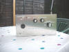
The new VHF/FM Pulse Counting Superhet Receiver, Now in its own aluminium case. This is a conversion from the early Superregenerative Circuit.
|
|
|
|
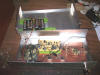
Inside view of the VHF Superhet conversion. All RF circuitry is hard wired on laminated board. IF AMP and AF circuitry is wired on plain veroboard.
|
|
|
|
|
|
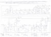
Circuit diagram of the simple Pulse Counting FM Superhet Receiver. The earlier Super Regenerative and RF Amp form as an Autodyne Converter.
|
|
|
|
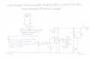
Circuit Diagram of recommended LM380 Audio Amplifier Circuit, Suitable for all versions of these VHF Receivers.
|
|
|
|
Wiring diagram of the simple Pulse Counting FM Receiver. Note that this is the RF circuits. You need to refer to picture 9 for IF and AF Amp circuitry
|
|
|
|
Wiring diagram of IF and AF amplifier Circuit board for a simple FM Pulse Counting Receiver Conversion. Please refer to picture 8 for RF section.
|
|
|
Please left click on selected picture to enlarge image.
Please Refer To The Following Video Clips Below
To See these Receivers Working
My Solid State FET Superregenerative VHF Receiver.MP4 - YouTube
My Demo Of Receiving High Quality FM Reception Using Straight
Regeneration.MP4 - YouTube
My FM Superregenerative Receiver Converted To A Solidstate Pulse
Counting Receiver.MP4 - YouTube
Construction Details Of The Simple 3 Transistor
VHF Super Regenerative Receiver
Before commencing with the construction of
these simple VHF Receivers it is advisable to check the component availability
first by clicking on the following link
Components List Of The
Simple VHF Receiver Projects which gives you the full list of components and
a list of well known internet component suppliers. Apart from the tuning
capacitors and depending on what transistor is used for the TR2 VHF Detector all
components should be available from the following link
Maplin Electronics at this
time of writing.
Important Guidelines Regarding
Safety And Construction Layout Of This Simple VHF Receiver
Because VHF receivers use a much higher frequency
then the Medium Wave and HF Shortwave bands it is not advisable for an absolute
beginner to radio work to attempt the construction of this receiver unless they
have had, At least experience with constructing the earlier featured
regenerative receiver projects for the following reasons. The safety regarding
the careful use of alkaline batteries and ensuring the correct polarity remains
the same as for the earlier receivers except the construction of the RF circuits
is very critical which I will briefly explain. Compared to the Medium and HF
Shortwave bands every millimetre of lead counts as an inductance, So all wiring
of the tuned circuits must be as short as possible and laminated copper
cladboard forms an excellent ground plain in this respect and must be used for
all the VHF circuitry. Normal veroboard can be used for all audio circuits as
they do not carry RF currents in the same way as high frequency radio waves.
Because this simple design is of the Superregenerative type of receiver, The
risk of interference to other nearby FM receivers is very high and a metal case
must be used for housing this receiver along with an RF Amplifier stage to
isolate the antenna from the detector. As another precaution, Avoid using this
receiver in the close proximity of airports particularly if you have it tuned to
the aircraft navigation band as this could cause illegal interference to air
traffic control. Also do not expect this type of receiver to give the same hi fi
audio quality and sensitivity like my other receivers such as the
6 Valve VHF/FM Pulse Counting FM
Tuner Using Safe 25Volt DC HT Line although having said that, If you
happen to have a very good antenna system or live in a very good reception area
this type of receiver can be used in normal regeneration mode using slope
detection of the FM carrier and very excellent audio quality can be expected.
Also if you are very lucky to live near a nearby strong signal transmission it
is possible use my Special FM Stereo Decoder
Circuit For Pulse Counting FM Receiver . I myself have experienced very good
Hi Fi quality stereo reception when using the receiver in this mode and another
advantage is because the detector is not oscillating you are not radiating
illegal interference to nearby receivers. This receiver can also be modified to
a slightly more advanced superhet design using the low frequency IF no coils
pulse counting technology which will give even better performance regarding
sound quality. One final note regarding the choice of FET Transistor used for
the TR2 VHF Detector. The popular 2N3819 FET is the easiest transistor to obtain
but its sensitivity is not as good as the BF244 particularly when using this
receiver with a short telescopic antenna and stations are rather weak. The
BF244B FET transistor is still available at the time of writing from the
following link
Cricklewood
Electronics and is highly recommended particularly if you intend upgrading
this version of the VHF Receiver to the later superhet pulse counting receiver.
General Construction Of The VHF
Superregenerative Receiver
1. Before attempting construction of this simple
VHF Receiver project it is advisable to have all the components needed at hand
which are listed on the following link
Components List Of The
Simple VHF Receiver Projects .
2. Please refer to picture 2 for the complete
wiring diagram of the basic receiver.
3. As you can see all the basic RF section is
hard wired on copper cladboard and this includes the mounting of all the
controls as well. Tagboard is also used for supporting the components and points
marked E are chassis earth points.
4. The AF Audio section is wired on a veroboard
which must be supported on the chassis with suitable bolts and is mounted on the
top right side of the chassis with the volume and on/off switch above the
circuit board as shown in the diagram. Also spacers must be used to isolate it
from the chassis and PVC tape bonded around the board mounting area of the
chassis is advisable. Also the complete audio board will serve for the later
featured Pulse Counting Superhet Receiver so if you intend to do a later
conversion, It will be advisable to leave plenty of space on the
board for the IF Intermittent Frequency Amplifier.
5. The audio section must be wired up first as
there is no way of knowing the receiver properly works without it unless you
have a suitable audio source to hook the receiver up to. Please refer to picture
3 which is the complete wiring diagram of the entire audio section.
6. As you can see in the diagram of picture 3 the
orientation of all semiconductors regarding correct polarity is explained, For
instance the TR3 BC547 Preamp silicon transistor polarity is viewed from the top
of the circuit board. The IC1 LM380N is also viewed from the top and a small
half moon mould identifies its orientation. Also a 14 Pin DIL socket is
recommended as this IC does not like too much prolonged heat when soldering. As
like I have explained before in the earlier articles of the previous
regenerative and crystal set circuits you must also pay attention to the correct
polarity of the electrolytic capacitors making sure the positive + corresponds
as shown in the circuit diagram. Picture 7 is the circuit diagram of the audio
power amp circuit and I will just mention the purpose of the 4.7uh RF choke in
the positive line of the speaker. It helps prevent VHF RF currents from
circulating in to the output stage which is a known problem of instability which
occurs when using short antennas and also when the volume is at a very high
setting you may experience squealing which is described as VHF parasitic
oscillation. This is a well known problem with a lot of the audio ICs
particularly the LM386 used in my past FM receiver projects. Also all connection
points on the circuit board are marked in alphabetical order to make
interconnection to other stages easy and minimises mistakes. As I said
earlier, It is advisable to use twin stranded screened audio cable for wiring
the volume control and the braid must connect to the point G 0V line.
7. If you are confident you understand all the
information explained above then you may go with the construction of this stage.
Please refer to the information below for testing and setting up the audio
stage.
Testing And Setting Up The Audio Stages
1. If you are double sure you have checked
everything carefully such as the polarity of transistors, ICs and electrolytic
capacitors you may now go ahead with testing this stage.
2. Connect a suitable 8 Ohm speaker to the output
terminals H and J as shown in the picture 3 wiring diagram
3. Advance the RV2 preset potentiometer which
regulates the supply voltage to the preamplifier and also acts as a gain
control. Note that when this stage is connected to the receiver circuits this
control may need readjustment which is with trial and error.
4. Advance the RV1 volume control about midway
and taking care that you observe the correct polarity connect a suitable 9V
power supply and switch on.
5. If all is well you should hear a soft hiss in
the speaker. If this is so, Try touching point B with your finger or a
screwdriver blade.
6. If all is well you should hear a buzzing noise
which means this stage is working correctly and if this is so you may proceed
with the wiring of the VHF RF Circuits which is the next procedure.
Wiring Up The VHF RF Circuits
This is where the greatest of care must be taken
or the receiver will give very poor results or not work at all because as I said
earlier every millimetre of RF leads to the tuning capacitor and RF Tuning coils
counts as an inductance which results in high losses at VHF compared to the
earlier shortwave receiver circuits. To give you an example please refer to
picture 5 which is an inside view of my later pulse counting superhet conversion
design, In which the same precautions apply. Also each VHF stage must carry its
own earth return point to the chassis as shown in the wiring diagram of picture
2 or this again will stop the receiver working correctly as feedback from one RF
stage to another is very noticeable in the VHF Ranges. A brief note concerning
the TR2 Transistor which forms as the main detector in this VHF Receiver. The
2N3819 FET is satisfactory for tuning in very powerful nearby signals. However,
You may find the receiver performs a bit on the weak side when listening to
distant transmissions or when using the short telescopic antenna and for this
reason I do strongly recommend you using the BF244B which is an excellent
performer on the VHF Frequencies. Also the Biasing resistor R3 is different for
both these transistors and is highlighted in the components list and the picture
1 circuit diagram. Also the transistor base views are viewed at the bottom
for wiring this stage. Although a suitable heat shunt is advisable when
soldering these transistors, It is the correct polarity that is the most
important and you must double check this before applying power to the
circuit.
Construction Of The RF Tuning Coils And RFC3
Choke
The L1 RF Tuning coil covers 87 MHZ to 120 MHZ
when used with the specified 25PF air spaced tuning capacitor in the prototype
receiver. This includes the VHF/FM Band and aircraft navigation band. Also this
depends on the setting of the TC1 trimmer capacitor. It is also possible to pick
up the Marine and Taxi transmissions on about 150 to 176 MHZ but as the local
police are now using voice encryption techniques which were introduced in the
early part of this century all these services are gradually going the same way
and all you will hear is a unintelligible carrier which has took the fun out of
scanning. The RF coil is airspaced and is made up from the solid copper strands
of 6 mm UK Shower or Cocker type mains cable and about 6 to 7 turns is ideal for
the coverage mentioned. A 1.5 Volt AA size battery is used for the assistance of
winding this coil and its turns are spaced at about 1.5 mm. The RFC Regeneration
choke is wound with about 25 to 40 turns of 26 SWG enamelled copper wire and the
former can be a nylon rod of about 30 mm cut from a volume control potentiometer
with thin layers of PVC tape at each end to support the windings.
The Final Wiring And Initial Testing Of The VHF
Superregenerative Receiver
If you are now confident you have correctly wired up the VHF
circuits as shown in the wiring diagram of picture 2 you may now connect up the
audio stages ready for the initial test. Insulated tinned copper wire is used
for all these connections and it is best to use red for all positive
connections. Black wire is also used for all negative and earth return
connections. Please follow the step by step instruction featured below.
1. Please refer to the picture 2 wiring diagram.
2. From the junction of R2 and R3 which is the positive supply
line for the VHF RF circuits, Connect a red lead to point A on the audio board
as shown in the wiring diagram.
3. Connect a Black lead from the C8 Audio coupling capacitor
to the point B AF Input on the audio board as shown in the wiring diagram.
4. Connect a piece of bare tinned copper wire to the point C
0V Line to the point E earth point as shown in the wiring diagram.
5. Presuming you have already tested the audio stage it is now
time for the initial test.
5. Reconnect a suitable 8 Ohm speaker to points H and I
on the Audio Board which is the power amplifier output.
6. Connect about 1/2 a metre of insulated wire to the antenna
socket or if you have already enclosed the receiver in the recommended case
mentioned in the components list then fully extend the telescopic antenna.
7. Double check your work for any possible mistakes and if all
is well reconnect the power supply circuit.
8. Rotate the RV1 Regeneration control clockwise until you
hear a high pitched hiss which means the Superregenerative Detector is
oscillating.
9. If this is the case then try rocking the VC2 tuning
capacitor and it should be possible to tune in a few stations within the FM Band
or the VHF Marine Aircraft band.
10. Try moving the antenna around for maximum signal strength
until you get a clear undistorted signal with the absence of any background
hiss. Also if the audio sounds a bit weak, Even with the volume near its full
setting try readjusting the RV2 Gain control on the audio input preamplifier.
11. If all the above tests and procedures have gone ok it is
now time to align the VHF tuning range so the correct coverage is obtained which
I will briefly explain how this is achieved.
12. The frequency is at its most highest when the vanes of VC1
are fully open. Closing the vanes of VC2 Decreases the Frequency coverage of the
receiver. The series trimmer capacitor TC1 in the tuned circuit also has the
same affect and is used to set the frequency band limit of VC2.
13. In the case of us wanting the receiver to cover the entire
FM broadcast band and aircraft navigation band you need to carefully follow
these next steps.
14. Try to tune in BBC Radio2 which broadcasts between 88 to
91.0 MHZ which is extreme lower part of the FM band.
15. If you are receiving Radio2 with the VC1 Vanes half way
open this needs correcting which I will describe in the next step.
16. Opening the Vanes of the TC1 highers the frequency
coverage of VC1 and you need to slowly maintain this trimmer and at the same
time and keep retuning radio 2 until you are receiving this station with the VC1
vanes open about 3mm from its lowest capacitance.
17. If all the above steps have gone to plan you now have a
simple VHF receiver of all your own work. Please refer to these next important
steps on how to get the best out of this receiver and simple tips on preventing
interference to other listeners.
Simple Tips On Getting The Best Out Of this
Receiver And Avoiding Interference With Nearby Listeners
Simple Superregenerative receivers can give the
newcomer to VHF Construction, Many happy hours of fun but there is a
disadvantage that this type of receiver can spoil a previous good friendly
neighbourhood relationship for the following reason. Like I have said before
Superregenerative detectors are always oscillating at a strong supersonic
frequency with a quench frequency of about 30 KHZ. Unless the proper precautions
such as enclosing this receiver in a proper metal case is not followed correctly
it is possible to interfere with nearby listeners that are tuned to the same
frequency. Even if you have took these precautions carefully it is also a good
idea to confirm this by trying a domestic home portable FM receiver around
different locations of the home to help confirm that you are not likely to
course illegal interference. Even with the receiver in a fully enclosed metal
case it is still possible to cause weak interference with a receiver that is in
very close proximity so please still take extra precautions. As a final note, Do
not let the cat out of the bag by asking your entire neighbourhood or showing
them your piece of achievement as you may be automatically to blame for any
future interference which is not necessarily your fault. If you are really
concerned about causing interference then this receiver can also be used as
normal regenerative detector in the same way as the earlier Shortwave
regenerative receiver projects which I will describe how this is achieved.
How To Use This Receiver In Normal Straight
Regeneration Mode
1. In the absence of a broadcast station advance
the RV1 in the clockwise direction until the superregeneration hiss just begins.
2. Very slowly back off RV1 in the anticlockwise
direction until the hiss just stops.
3. Try retuning in a strong FM signal which may
sound very distorted and unintelligible because the detector is still
oscillating in normal regeneration mode in the same way as the earlier medium
and shortwave regenerative receivers. In the simple case of this you need to try
backing off the RV1 Regeneration control slightly further and then it may be
possible to tune in the signal crystal clear with no distortion. This method off
receiving FM has its advantages and disadvantages which I will briefly describe.
The main advantage is the detector is not oscillating at all so there is no
chance of you causing illegal interference to nearby listeners. Also on very
strong signals very high quality sound reproduction can be archived and it is
even possible to use a stereo decoder due to the very high response curve. The
main disadvantage is the receiver is not as easy to use practically for the none
technical user for the following reasons. You need to keep readjusting the
regeneration control when tuning from one station to another and you need to
tune carefully on either side of the FM carrier for minimum audio distortion
which is described as slope detection. If you wish to experiment with stereo
reception then my Special FM Stereo Decoder
Circuit For Pulse Counting FM Receiver works very well with this receiver.
You will need to take off an audio feed point which can be obtained at point D
and the earth can be obtained at point F which is at 0V negative potential which
is where the outer braid of the connecting cable must branch off from. Please
also note that stereo only works well on the very strong transmissions and an
outdoor antenna is the best bet rather then relying on the simple telescopic
antenna. As a closing note I hope you enjoy building and using this simple VHF
Receiver project and it is convertible to a more powerful superhet broadcast FM
Receiver using no coils technology which will follow next.
Construction Details Of The Simple FM Pulse
Counting Superhet Receiver Conversion
Because this version of the FM receiver is a
simple upgrade conversion from the simple regenerative receiver there will be
little mentioned on the setting up procedure because if you have already built
and got that design correctly working the mixer and oscillator circuits will be
already aligned. If you are intending to upgrade the regenerative receiver you
need to refer to picture 6 for the circuit diagram as there are 2 slight
component changes required in the VHF RF Circuits and you must follow these step
by step instructions very carefully.
1. Resistor value of R5 must be changed to 2K2.
2 Capacitor value of C7 must be changed to 1NF and C8 must be
changed to 470PF.
3. The inclusion of the resistor RX may not be needed but may
help to prevent the VHF mixer and oscillator breaking into superregeneration
particularly when using BF244 as the mixer transistor or when new batteries have
been installed. The value of this resistor is 1K.
4. As I assume you will already have the audio preamp and
power amplifier constructed you only need the additional components listed below
but please note the following. To avoid confusion of component values and
duplicate numbering with the earlier design please make sure you are referring
to picture 6 for the complete circuit diagram. You will also need to refer to
picture 8 which is the wiring diagram for the superhet receiver configuration
but please note the following. Because of drawing space I have compiled a
separate wiring diagram for the IF and AF Circuitry in which you must refer to
picture 9.
Additional components for the inclusion of an
IF Amplifier stage needed for conversion
Resistors. All 1/4 cracked carbon
R6 R8 R10 R13 1M.
R7 R9 R11 33K.
R12 82K or 100K preset pot.
R14 R15 10K. R16 4K7. R17 R18 47K.
Capacitors
C9 C10 C11 470PF Ceramic disc.
C12 C14 100uf 25V Electrolytic.
C13 C15 100NF Ceramic disc.
C16 22PF Ceramic disc.
C17 1000PF Ceramic disc or 100PF if you want to
experiment with a stereo decoder.
C18 100PF Ceramic disc.
C19 100NF Ceramic disc.
Semiconductors
TR3 TR4 TR5 TR6 TR7 BC548
D1 D2 OA90 or OA91 Germanium Diode.
5. The above components list is for the additional components
required to upgrade the existing Superregenerative receiver to a pulse counting
superhet receiver version only.
6. If you are building this version of the receiver straight
from scratch and have not yet built the earlier Superregenerative receiver then please refer to the
Components List Of The
Simple VHF Receiver Projects and look under the heading, Components List For
The Simple Pulse Counting FM Receiver which lists all the components required to
build the complete superhet receiver. Unless you are confident you can wire and
assemble the whole superhet receiver from scratch it is advisable to build the
Superregenerative receiver first and then follow steps 1 to 3 regarding the
necessary component change.
7. If you are now confident that you can do this conversion
you will need to temporarily disconnect the audio preamp and audio power
amplifier board making sure you have disconnected the batteries before
proceeding. To prevent any electrolytic capacitors on the board from recovering
a charge it may on a temporary basis be advisable to connect a resistor of about
10K between the positive 9V line and negative 0V line. You must remember to
remove this resistor when you come to reconnect everything or you may find
yourself replacing new batteries frequently due to more excessive current demand
then usual.
8. You now need to refer to picture 9 which is the wiring
diagram of all the IF and AF circuitry.
9. Assuming you have left enough room on the circuit board
after building all the audio stages, You may now proceed with building the IF
circuitry. Please pay the usual attention like you did when building the earlier
receivers regarding the component polarity of all semiconductors and try to keep
soldering time to a minimum of about 3 seconds when soldering the D1 and D2
Germanium diodes as these are very heat sensitive.
10. Special note regarding the C17 Reservoir capacitor in the
diode pump circuit and replacing R12 For a 100K preset pot. For normal mono
reproduction this value should be 1000PF maximum. However, If you wish to
experiment with a stereo decoder you need to make sure you do not increase this
value to more then 100PF or stereo will not work or the separation in both
channels will be very poor due to narrow bandwidth detection which will severely
distort the 19KHZ pilot tone and S Signal components which includes the 38KHZ
Sub carrier. Please note that this sort of receiver has its disadvantages when
configuring for stereo which I will briefly explain. Due to the 250KHZ IF
Intermediate frequency used, The bandwidth is much lower then receivers that
have a 10.7 MHZ IF and the FM signal itself requires 150KHz for a distortion
free signal. For the reason previously mentioned you need to be in a very strong
signal area or have a decent outdoor antenna to give a signal of no less then 60
to 70db or results will be very poor and you will find background hiss and pilot
tone noise very noticeable particularly on stations such as Classic FM and Radio
3 when there are quite intervals of soft music. Also if you are thinking of
experimenting with stereo it may be a good idea to replace R12 with a preset pot
or variable potentiometer as increasing the resistance will reduce the IF gain
which will narrow the pulses in the diode pump circuit leading to wider detected
bandwidth. Finally on this subject you will also need to take an audio feed from
point D and point E which must connect to the outer braid of the lowest
capacitance of screened cable you can possibly go for. A suitable stereo decoder
circuit can be found at the following link
Special FM Stereo Decoder Circuit For Pulse Counting FM Receiver .
11. If you are now confident you have rewired all the circuit
board with the new IF circuitry it is now time to reinstall the the IF and AF
circuit board ready for rewiring back to the VHF circuitry, Making sure you
remove the temporary resistor link between the positive 9V line and 0V line on
the circuit board.
12. The wiring to connections on the circuit board is carried
out in alphabetical order in the same way as the Superregenerative receiver so
mistakes are minimised and makes the wiring diagram more easy to understand.
13. If you are now confident you have completed all the above
tasks very carefully it is now time to test and set up this version of the Pulse
Counting FM Superhet Receiver. As a final reminder please double check the
circuit board for any slight mistakes such as wrong component polarity and any
possible solder bridges. please refer to the final testing and setting up
procedure
Final Testing And Setting Up The FM Pulse
Counting Receiver Configuration
1. Rotate the RV1 Regeneration control fully
anticlockwise.
2. Rotate the RV1 Volume control between mid to
high setting
3. Reconnect the batteries and switch on the
power
4. If all is well you should hear a mid to high
pitched hiss similar to the Superregenerative configuration which means the IF
Amplifier and diode pump circuits are working correctly.
5. Rotate the RV1 Regeneration control very
slowly until the high pitched hiss ceases which means the VHF Mixer and
oscillator are working in Superregenerative mode overloading the IF amplifier
stages which only needs some simple correcting which I will describe how to
perform in the next step.
6. Slowly back off the regeneration control
anticlockwise until you get to the point where the high pitched hiss
recommences.
7. Connect a suitable antenna to the VHF antenna
socket which can be a 1 metre piece of flex or the recommended telescopic
antenna with its length fully extended. Make sure the antenna is placed in a
vertical or horizontal position clear of any obstructions.
8. By rotating VC2 and assuming you have not done
anything to upset the tuning alignment since having it configured as a
regenerative receiver you should now be able to tune in the same stations as
before but with nice crystal clear reception. You may due to increased
sensitivity be able to hear stations that were previously very weak when you had
the receiver configured as a simple regenerative receiver.
9. Adjusting the regeneration control is with
trial and error but with a bit of practice your experience should gain. If you
go for the strong stations on the FM band you will not need to hardly adjust it
at all but you may find that the oscillation may cease when tuning from one end
of the band to the other. Now that this receiver is a superhet configuration,
This control is also now referred to as the oscillator amplitude control and
having the oscillator set at its lowest amplitude as possible will reduce the
likelihood of illegal radiation which is very low compared to the
Superregenerative detector and also the 10.7 MHZ commercial standard broadcast
receiver can experience similar problems.
On A Final Closing Note
I wish you all the success in building these
simple VHF Receiver projects and that you also enjoy using them as well. This
final solid state version of the FM pulse counting receiver is my best portable
VHF receiver project to this very day and works very well in even the poorest of
reception areas. This receiver also marks the final solid state project on this
page.
Simple Valve Receiver Projects Designed For
Safe Low Voltage Operation
Welcome to the last series of simple radio receiver
projects on this page involving the use of valves, Our long and beloved devices.
The first project is a simple low voltage regenerative receiver capable of
receiving the Short and Medium Wavebands and will work on an HT voltage as low
as 10 Volts. The second receiver project is almost the same design except it has
a higher power output using an ECL82 output stage and will work on an HT Voltage
of between 30 to 65 Volts. The third and final design is a VHF/FM version of the
2 valve regenerative receiver. Although these projects involve the safe use of
batteries a mains power supply unit is featured for the more experienced
constructors that know the dangers involving mains electricity and have at least
built a mains powered project.
|
|
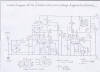
|
|
Circuit Diagram of the simple low HT 2 Valve Regenerative Receiver. Battary operation is possible with this receiver making it a safe starter project
|
|
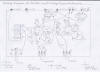
|
|
Wiring diagram of the simple low HT 2 Valve Regenerative Receiver. Please refer to picture 1, The circuit diagram for component values.
|
|
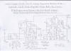
|
|
Circuit Diagram of low HT 2 Valve Regenerative Receiver. This version has an ECL82 power amplifier resulting in improved audio volume.
|
|
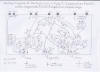
|
|
Wiring diagram of the simple low HT 2 Valve Regenerative Receiver with ECL82 Audio output. Please refer to picture 3 for component values.
|
|
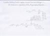
|
|
Suggested Battery power supply circuit providing LT low tension 6V DC supply for heaters and a 27V DC HT supply for the receiver circuitry.
|
|
|
|
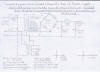
|
|
Circuit diagram of suitable mains power supply for powering low HT Valve circuits. NB This circuit must be constructed under adult supervision.
|
|
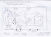
|
|
Wiring diagram of the mains power supply unit. Please refer to picture 6 the circuit diagram and components list for more information.
|
|
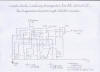
|
|
Band switching circuit to allow full coverage of the HF Shortwave Spectrum including Medium Waves using a total of 4 band coils.
|
|
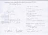
|
|
RF Coil Winding details for both versions of the 2 Valve Shortwave Regenerative Receiver. Please see text for more details.
|
|
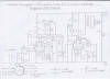
|
|
Circuit diagram of VHF/FM version of the 2 valve low HT Regenerative Receiver. NB Only performs well with outdoor antenna or in good reception area.
|
|
|
|
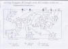
|
|
Wiring Diagram of VHF/FM 2 valve low HT Regenerative Receiver. Please refer to picture 10 the circuit diagram and components list for more information
|
|
|
Please left click on selected picture to
enlarge image.
Please refer to the following links below which
are video clips of these receivers working
My New Design Of A 2 Valve Regenerative Receiver Working A
Loudspeaker At 10 Volts HT.MP4 - YouTube
My Success With FM Stereo Using A 2 Valve Regenerative Receiver
Driving An MC1310 IC Stereo Decoder - YouTube
Construction Details Of The Simple 2 Valve Low
HT Regenerative Receiver
Before attempting the construction of these
simple low HT valve projects please refer to the following link
Components List
For The Low HT 2 Valve Receivers and the important safety guidelines
regarding the safe use of Acid Lead Batteries and the Low HT Mains Power Supply
Unit.
Important Safety Guidelines Regarding The Safe
Use Of Acid Lead Batteries And The Low HT Supply
Although these simple valve receiver projects use
much lower HT voltages then the dangerous 250V DC supply found in mains powered
receivers, The 6V heater supply involves the use of acid lead batteries which
are not suitable for young children or inexperienced constructors to experiment
with unless the following precautions are taken for obvious reasons which I will
briefly mention. They are capable of delivering very heavy currents then the
alkaline batteries used in the previous solid state regenerative receivers
featured on this page in which you must observe the following precautions.
1. You must at all times be very careful not to
accidently
short circuit the terminals or this may produce large sparks and even rupture
the cells which could lead to a fire hazard and the leakage of toxic acid.
2. You must also never wear jewellery such as
metal watch straps when handling these batteries for the previous reasons
mentioned and you must use the proper connecting crimps rather then just
wrapping the wires loosely around the terminals as overheating may occur due to
heavy current demand.
3. To ensure maximum protection against short
circuits you must ensure that you use an inline fuse in the positive lead, Preferably
in a plastic sealed enclosure before it enters the receiver which is the type
used with car radios and is available from motor garage stores.
4. You must also make sure you use 6 Amp bell or
stranded wire for wiring all valve heater connections and a suitable good
quality switch must be used in the positive line capable of at least
withstanding 3 Amp DC or contact welding may occur.
5. You must also make sure the recommended mains
charger is used for charging these batteries and you must ensure the correct
manufacture instructions are also followed.
6. If you feel intimidated about using acid lead batteries
then 4 X 1.5V size C will work, Although you may find it expensive constantly
replacing them unless you use the rechargeable type and you may only get an hour
or so of listening.
7. The low voltage HT supply poses less of a problem apart
from the higher powered version of this receiver that uses 54 Volts which I will
briefly explain. Although 54 Volts is not dangerous like the common 250V supply
found in mains powered valve receivers, Still do be careful as it is still
possible to get an unpleasant nasty jolt. The same rules apply as mentioned in
the solid state receiver article regarding the correct polarity of components
such as electrolytic capacitors, But there is a good advantage about valves in
this respect. As there electrodes are all of metal construction, Current only
flows in 1 direction so it is impossible to damage these devices except the
heaters may be blown if HT voltage is accidently applied to them, So still
please do be careful and check your work constantly for possible mistakes. Also
the ECC86 Triode must not exceed a maximum 30V of HT or melting of the anode may
result.
8. Because valves use much lower HT currents then solid state
devices you will find the batteries will last a very long time and PP3
transistor radio batteries connected in series will be suitable. Also because of
the higher voltages incorporated with these simple valve receiver circuits it is
still advisable to incorporate a fuse in the HT line for maximum protection
against valve HT shorts although this is only common in guitar amplifiers which
was mainly due to them being moved around from 1 venue to another.
9. Please refer to picture 5 for the recommended
battery power supply circuit arrangement for powering these simple valve
receiver projects. Pictures 6 and 7 are for a mains power supply unit that will
in the long term reduce the cost of running these receivers on batteries but
please refer to the following notes regarding safety. Although the LT and HT
output is reasonably safe it still has 240V AC mains present on the primary side
of the mains transformers and the circuit must only be attempted by experienced
constructers who know the dangers of high voltages and have some experience with
constructing mains powered projects. There will be construction details
available for this circuit later on in this article.
10. As long as you fully understand these simple
precautions you may now go ahead with the construction of these simple valve
receiver projects which should provide you many hours of fun and over all, Great
achievement in building your first valve radio.
Building The Receiver Of Your Choice
First time constructors to valve circuits and radio
construction are best attempting the HF Short and Medium Wave version of these
receivers first as the VHF/FM version requires care in the construction of the
RF circuits regarding the layout and wiring. If you are building the first
version of this receiver you need to refer to picture 1 for the circuit diagram
and picture 2 for the wiring diagram. If you intend to build the higher powered
audio ECL82 version you need to refer to picture 3 for the circuit diagram and
picture 4 for the wiring diagram. Please refer to the next article which
describes the chassis construction details.
Preparing And Constructing The Chassis
The hardest part of building any valve receiver
is cutting and preparing the chassis. Alternatively if you wish to house this
receiver in a wooden case you can use cladboard which also forms an excellent
ground plain. Also Because of the low voltages involved you can use the old
breadboard method of construction on both versions of the short and medium wave
version. If you are intending to build the VHF version of this receiver I am
afraid to say that a proper metal chassis or cladboard will only work as VHF
circuits must relie on a solid ground plain with short point to point wiring
because of the very high frequencies involved. It is best to have all chassis
mounting components to hand such as controls, valve holders and tuning
capacitors so you can get a rough estimation on hole sizes required before
starting the drilling. The chassis punch tools for drilling holes to accommodate
the valve holders will save you hours of filing but I am afraid to say that they
are not as easy to get hold of like they once was when valves were a popular
electronic device. A suitable chassis case is available from the following link
Maplin Electronics and the order
code is KR56L. Please refer to the following step by step procedures listed
below.
1. If you have now confidant that you have all
components available, The chassis drilling can now go ahead.
2. You need to refer to picture 2 the wiring
diagram if building the basic low powered ECC86 amp version or picture
4 which is the wiring diagram for the higher powered ECL82 version.
3. The highlighted connection Points marked E are
chassis negative earth return points and are usually a solder tag and bolt. You
must ensure all these connections are screwed tight and are clean or sparking
may result, Particularly within the valve heater connections as these are the
most current hungry of the entire receiver. As the tuning capacitor and coax
socket in the VHF design are of metal construction they will be automatically
earthed to the chassis so it is just a matter of making sure the mounting bolts
are screwed tight and the right connection tag is used for connecting the earth
returns on the tuning coils
4. If all the above procedures have been
correctly followed you may now go ahead with wiring and testing the valve
heaters which will follow next.
Wiring And Testing The Valve Heaters
1. Although this is the easiest part of the
wiring in the entire receiver you must ensure the correct size wire is used as
mentioned earlier and all connections must be soldered as neat as possible with
no dry joints.
2. As the chassis forms a negative earth return
for the valve heaters you must make sure all solder tags are clean free of
grease or sparking may result. Also the 100NF bypass capacitors must not be
omitted or hum modulation may result particularly when using the mains power
supply unit as the supply is 6.3V AC.
3. If you have followed the above procedures
correctly you may now give this stage of the wiring a continuity and initial
test.
4. You will need an analogue test meter set to
the low ohms reading. If you are building the low powered version of this
receiver you need to connect your probes in either polarity to SK5 and SK6. If
you are building the high powered ECL82 version of the receiver you need to
connect your probes to SK3 and SK4.
5. At this stage you should get a zero ohms
reading. If for some reason you get a full reading at this stage then you have a
fault and it must be investigated before proceeding any further.
6. Insert V1 and you should now get a reading of
around 18 ohms. If this is so proceed to the next step.
7. Insert V2 and you should now find that the
previous reading should drop to around 9 ohms. If this is so then this stage is
wired and working correctly.
8. Carefully remove both valves and store them in
there respective cartons until they are next needed. Proceed to the next step
which is initial wiring and testing of this receiver.
Initial Wiring And Testing Of this Receiver
Assuming you have followed the last procedures
regarding the wiring of the valve heaters and that the testing has gone ok you
can now go ahead with the basic wiring of the receiver. As you are working at
rather high frequencies try to keep all wiring in the RF tuned circuits as short
as possible. When you come to initially test the receiver it is better to build
it as a single band receiver and if your interest lies mainly in shortwave
listening, The SW2 RF coil gives 24 hour coverage around all 4 corners of the
globe and is also very easy to wind. You must pay very carful attention to the
polarity of the electrolytic capacitors as these can heat up and explode as I
mentioned earlier in the solid state article. If you are building the high
powered ECL82 version then you need to ensure all electrolytic capacitors where
highlighted are rated at 100V as a safety margin and that applies to all grid
and anode bypass capacitors. You need to refer to picture 1 the circuit diagram
and picture 2 the wiring diagram if you intend constructing the low powered 27V
HT version of this receiver. Pictures 3 and 4 are the circuit and wiring
diagrams if you intend building the 54V HT high powered version of this
receiver. Picture 9 is the full coil winding details and you must ensure you use
the correct gauge of wire as stated for maximum efficiency. The wire for winding
all coils is available from the following link
Maplin Electronics . Picture 8
is a simple band switching circuit for all the HF and Medium frequency range
between 550 KHZ to 30 MHZ and it is best to test all coils individually before
wiring it up. A 3 Pole 4 way switch is required and I must stress that you must
try to keep all RF leads to the tuning capacitors as short as possible. As a
precaution try to wire the switching arrangement in a way that the shortest
leads are wired to the highest frequency coils rather then the reverse. 15
Millimetre plastic tube available from DIY Supermarkets is recommended for the
coil formers and tie warps will hold the wire very secure as to using glue which
can be very messy. Please refer to the last following procedure for testing and
setting up this receiver.
1. Assuming you have wound the tuning coil of
your choice and are certain that you have wired everything correctly you may
give your newly constructed valve receiver a first time try which should be the
moment of truth. As a final reminder please double check the wiring for any
possible short circuits or any wrongly connected components such as the tuning
capacitors.
2. Connect a suitable 8 Ohm speaker to SK7 and
SK8 terminals.
3. Connect about 2 metres of wire to the SK1
antenna terminal
for a temporary antenna for the time being.
4. Insert both valves into there respective
holders.
5. Connect the green negative 6V heater supply
lead to SK6 and the other end to the negative terminal of the acid lead battery
taking the greatest of care not to short the supply. NB
This terminal is SK3 on the 54V ECL82 version of this receiver.
6. Connect the yellow positive heater supply lead
making sure this side of the supply is correctly fused with the correct 2 amp
fuse as stated
to the SK5 terminal. Connect the other end to the positive terminal of the acid
lead battery. NB This terminal is SK4 on the 54V
ECL82 version of this receiver.
7. Switch the heater supply on and if all is well
the valve heaters should start to glow red which means this side of things is
ok.
8. Switch off the valve heater supply for the
time being until the HT side of things is fully connected.
9. Advance the RV1 regeneration control about
midway and the RV2 volume control fully clockwise.
10. Connect the black negative HT lead to the SK3
0V terminal. Connect the other end to the negative terminal on the 27V HT battery.
NB This terminal is SK6 on the 54V ECL82 version of
this receiver.
11. Connect the red positive HT lead to the SK4
HT positive terminal. Connect the other end to the positive terminal of the 27V
HT battery making sure the correct 100 milliamp HT fuse is connected in series
and a suitable rated on/off switch is used. NB This terminal is SK6 on the 54V ECL82 version of this receiver.
Stand by for the moment of truth.
12. If everything has gone to plan your valve
receiver
should now be working and by rocking the VC1 tuning capacitor you should be able
to tune in a few stations
13. Try rotating the RV1 regeneration control
until the receiver starts to oscillate, that can be identified by a continues
beat noise.
14. Backing off RV1 until the oscillation stops
is the most sensitive working limit of the regenerative detector and stations
should be received at very good signal strength depending on the time of day
when listening on shortwave.
15. If you are finding it impossible to obtain
oscillation at the lower end of the frequency range you will need to add 1 or
more turns on the earthy end of the L1 tuning coil. On the other hand, If
oscillation is uncontrollable you need to take a turn or more off the earthy end
of the L1 tuning coil.
16. If your interest is listening to amateur
radio hams then it is possible to resolve SSB Single Sideband. 3.5 MHZ 80 metres
is best during the evening hours and 14 MHZ 20 Metres is best during the
daylight hours. Strong sideband signals are identified in an unintelligent
distorted speech when the regenerative detector is not oscillating but can be
resolved by rotating the RV1 regeneration control clockwise until the set goes
smoothly into oscillation. You may then have to tune through the signal very
careful and compared to normal AM reception SSB stations sound more like Donald
Duck or if you are talking in a tunnel.
17. This now completes this article regarding the
simple 2 valve regenerative receiver project and I wish you all the success in
getting your first valve receiver working and many hours of listening enjoyment.
If your interest lies within listening to VHF/FM then the next article features
a 2 valve regenerative version which is constructed in slightly different way to
this version regarding the RF circuits. To close this article on low voltage
valve AM and Shortwave Receivers why not visit this link
12V
Superheterodyne Receiver designed by my favourite radio enthusiast John
Hunter. His excellent website has only just been redesigned at the time of
writing and I have only just learned he has just included a 12V VHF/FM Super
Regenerative Receiver similar to the design that follows and can also be found
at the following link
12v B+ Super
Regenerative Receiver
2 Valve VHF/FM Regenerative Receiver
This simple 2 valve VHF regenerative receiver is
constructed in the same way as the previous valve receiver projects and as the
safety precautions regarding the safe use of the Acid lead Batteries remain the
same, Little will be mentioned on that side of things except that this circuit
uses very high frequencies and all RF circuits regarding coils and circuit
layout must be arranged in a way that leads to the tuning capacitors must be as
short as possible. Band switching and using the long wire medium and shortwave
techniques will result in the receiver giving very poor performance and in some
cases not working at all. Also do not expect to get the same performance
regarding sensitivity like you would when using receivers such as my
6 Valve VHF/FM Pulse Counting FM
Tuner Using Safe 25Volt DC HT Line unless you have a suitable outdoor
antenna designed for receiving VHF/FM transmissions. In very good reception
areas it is possible to use a short 1 metre piece of wire or better still, A
telescopic antenna. Another closing note regarding the regenerative
detector configuration. The regenerative detector works in the same way as in
the previous valve receivers except positive grid bias is obtained from the
anode rather then leaky grid bias through the R5 270K resistor. Increasing R5 to
around 470K or more will make the sett operate in Superregenerative mode except
I found performance to be very poor regarding sensitivity and sound quality was
nothing to be desired compared to using the straight regenerative technique.
Before attempting the construction of this receiver please refer to the safety
guidelines mentioned in the earlier valve receiver article and the
Components List
For The Low HT 2 Valve Receivers . You also need to refer to picture 10 for
the circuit diagram and picture 11 for the wiring diagram. Please refer to the
next procedure which is the construction details of the VHF RF Coils.
Construction Details Of The VHF RF Coils
The RF coils used in this design are self supporting and ether
18 SWG tinned copper wire can be used or the bare strands of 30 Amp cooker
mains cable. A spare Size AA penlite battery will assist in winding the coil. L1
consists of about 7 turns and is slightly spaced at about 2 millimetres between
the windings. The L1
antenna tap is taken about 2 turns from the hot end of this coil which ever gives best
results. L2 is wound in the same way and consists of about 7 turns. The cathode
feedback tap for L2 is taken about 2.5 turns from the earthy end of the coil as shown
in the diagram. Assuming you have now completed all the above procedures
carefully and checked your work for any wiring errors such as ensuring the
correct polarity of the electrolytic capacitors, You may now go to the next and
final procedure which is the testing and setting up of this VHF Receiver
project.
Testing And Setting Up
1. Connect a suitable VHF antenna to the coaxial antenna
socket and insert the 2 valves into there respective holders.
2. Advance the RV1 regeneration control fully clockwise.
3. Advance the RV2 volume control fully clockwise at maximum
volume.
4. Connect a suitable 8 Ohm speaker to terminals SK5 and SK6
which is the speaker output.
5. Connect the green negative 6V heater supply lead to the SK1
0V heater terminal. Connect the other end to the negative terminal of the 6V
battery.
6. Connect the yellow positive 6V heater supply lead to the
SK2 positive heater terminal. Connect the other end to the positive terminal of
the 6V battery making sure this side of the supply is well fused with the
recommended 2 amp fuse and has the correct rated switch.
7. The valve heaters should start to glow red within around 10
seconds which means this side of things is working ok. If this is the case, You
can now turn off the valve heater supply for the time being until the 27V HT
side of things is connected up which should be the moment of truth.
8. Before proceeding with the 27V HT connections it is
advisable to double check your work for any possible mistakes such as wrongly
connected electrolytic capacitors and short circuits.
10. Connect the black HT negative lead to the SK4 0V terminal.
Connect the other end to the negative terminal of the 27V HT battery.
11. Connect the red HT positive lead to the SK3 HT positive
terminal. Connect the other end to the positive terminal of the 27V HT battery
making sure this side is fused correctly with the correct rated 100 milliamp
fuse and has a suitable rated switch incorporated.
12. Switch the 6V heater and 27 Volt HT supply on.
13. Allow 1 minute or so for the valves to warm up
14. Try rocking the VC1 tuning capacitor and you should be
able to tune in at least 1 of the stronger FM stations but with distorted
intelligibly until the next following step has been corrected.
15. Slowly rotate the regeneration control anticlockwise to
the point where the receiver stops oscillating and it may be possible to tune in
the station very clearly. Note that because you are using slope detection it
will take a bit of time to get used to tuning this receiver correctly as you
have to accurately tune to ether side of the FM carrier. Also like the short and
medium wave receiver projects the regeneration control needs to be readjusted
each time the receiver is retuned to another station. Now you have got this FM
receiver project working ok please go to the final part of the setting up which
is the RF tuning alignment.
RF Tuning Alignment
If you have built the earlier solid state FM
receiver projects the tuning alignment is almost the same but as this version
may be a first time FM receiver project for some constructors I will do a brief
rundown on the final stage.
1. Tune in a station around the mid part of the
FM band which is around 96 MHZ.
2. Adjust TC1 the antenna trimmer for maximum
signal strength.
3. Try tuning in BBC Radio 2 which is at the
lower end of the FM Band between 88 to 90.2 MHZ.
4. TC2 which is connected in series with the VC1
tuning capacitor is used to correct the FM tuning range which I will briefly
explain. Opening the vanes of TC2 swings the FM coverage in the high frequency
direction. Closing the vanes of TC2 swings the FM coverage in the low frequency
direction. If you find for example that you are receiving BBC Radio 2 with the
vanes of VC1 halfway open then this is very easy to correct. Readjust TC2 by
opening the vanes very slowly. You then need to retune to Radio 2 and keep
maintaining this procedure until you can receive this station with the VC1 vanes
open around 5 millimetres from the closing point of VC1. As the FM band is very
broad compared to the low frequency medium waveband, TC1 should not need
realigning all that much but it may worth retuning to some of the weaker
stations around the middle of the FM band and readjusting this trimmer for
maximum signal strength
5. If all has gone well with the previous
alignment steps, Then the receiver is ready to use and I wish you all the best
of listening enjoyment out of this simple valve FM receiver project. Before I
close this series on the simple valve FM Receiver project please refer to the
simple procedures below if you intend connecting this receiver to an external
amplifier or using a stereo decoder.
Connecting This Simple FM Receiver To An
External Amplifier or Stereo Decoder
This simple FM receiver is capable of giving very high quality
sound when connected to an external HI FI amplifier and if the signal strength
is very good, A stereo decoder will also work. Just 2 simple precautions
regarding safety before proceeding. Do not attempt to connect to any valve
amplifier or radio that incorporates a live chassis or a serious electric shock
hazard will exist. The way of finding this out is to look on the back of the set
and if it says universal AC/DC mains then it certainly is unsafe to use. Also
the UL84 and UY85 100 Milliamp heater type valves will exist that obviously
gives evidence. Also a 0.1uf coupling capacitor of at least 500V rating must be
used. Please refer to the simple procedure below.
1. Connect a 0.1uf 500 or 1000V polypropylene capacitor to the
pin 1 anode pin of V2 for an audio take off point. Connect the centre strand of
a suitable screened audio cable to the other end of the capacitor. Connect the
outer braid of the audio cable to the 0V line. It may also be better in the long
run to incorporate an RCA Phono socket on the back of the receiver for this
purpose. You will have to mute the internal speaker by using a switching network
to an 8 Ohm 1 watt resistor but as the audio output is so low there is very
little risk of saturating the core of T1 unless a higher powered amplifier is
used for the output stage. When connecting the receiver to a stereo decoder you
must make sure that the screened cable capacitance is not to high or very poor
stereo separation will result and you must make sure that this lead is as short
as possible preferably not more then quarter of a metre between the decoder and
receiver. A suitable decoder that works can be found at the following link
FM Stereo Decoder Circuit and also to give you an idea of how this same receiver
performs in stereo please refer to the following link to see this video
My Success
With FM Stereo Using A 2 Valve Regenerative Receiver Driving An MC1310 IC Stereo
Decoder - YouTube .
Suitable AC Mains Power Supply Unit For Powering
All The Valve Receiver Projects
This final project on this page is an AC mains power supply
unit suitable for powering all your valve receiver projects on this page and in
the long run, It will eliminate the use of batteries particularly when using
your valve receiver indoors saving you the cost of constantly replacing them and
the time it takes recharging the 6V heater battery. This simple power supply is
very easy to build but please note the following points before attempting the
construction. You must remember that high voltages can kill and because this
project involves the use of 240V AC mains electricity it is not suitable for
anyone who has had no experience with building mains powered projects or does
not fully understand the dangers that high voltages can pose. As a final
reminder, If you think you are unconfident with building this project then at
least stick to using batteries or get someone who is experienced to build and
test it for you. Please remember that you are taking your own risk and although
you may get this power supply working ok this does not necessarily mean to say that it
will be safe to use unless the following precautions are taken which are listed
below.
1. It must be built in a metal case designed for
this purpose with suitable ventilation and the vent slots must be small enough
so that small fingers can not access any live parts or connections.
2. The metal case and 0V negative line must be
soundly earthed by the green/yellow mains core and the earthing bolt on both
mains transformers must be very securely tight. Also make sure the solder tags
are clean with no signs of grease or dry joints or the earth will not be very
effective. Also the mains plug must be fused at 3 or 5 Amps maximum and must be
a proper 3 pin non reversible type.
3. You must also use use a proper rubber grommet
for entry of the mains cable rather then the simple tying a knot idea which used
to exist in projects featured in radio magazines during the valve era of the
1950s which I am afraid to say that electrical safety rules were not as strict
in those days as they are now.
4. Also to protect the power supply unit from
current overloads or the possible risk of fire you must ensure that the mains
and HT fuses are rated correctly. Do not cut the corners by using old tricks
such as cigarette paper or any foreign object or you may burn out your mains
transformers and there could be a possible risk of fire. The 250 milliamp mains
fuse FS1 which is in the live side of the mains protects the primary side of the
transformer against any possible overload or fault. The 100 milliamp HT Fuse FS2
in the secondary HT output protects the bridge rectifier and mains transformer,
So any heavy overload or short circuit will blow this fuse immediately. If this
fuse keeps frequently blowing there is a fault and it must be investigated
before proceeding any further.
5. If all these precautions are followed
correctly then this power supply circuit will be absolutely safe to use as
batteries, Provided it is not exposed to wet or damp conditions.
6. If you feel confidant about building this
circuit then you may now refer to the following construction and testing procedures
listed below but if you do feel in doubt, Stop now as you are taking your own
risk.
Constructing The AC Mains Power
Supply Unit
1. Please refer to picture 6 for the circuit
diagram and picture 7 for the wiring diagram.
2. Points marked E in the wiring diagram are
chassis earth points and you must make sure that the ones that accommodate both
mains transformer bolts have a solid bond to the mains earths green and yellow
core. Also you must ensure that that the HT 0V Line and 0V LT Heater Line is
also earthed to this point as shown in the circuit and wiring diagram. If this
step is followed correctly there should be no danger of the case and your radio
receiver project becoming live at mains potential, In the case of a serious
fault within the mains transformers.
3. It is better to have all chassis mounting
components to hand before starting the construction so you can get familiarise
yourself with a good estimation of the hole sizes that need to be drilled in the
chassis. Also it is better to have all these components mounted on the case
before proceeding with the wiring. The bridge rectifier and HT smoothing
circuit, That is C1, C2 and the R1 smoothing resistor are mounted on plain
veroboard. As a final reminder you must make sure that the electrolytic
capacitors C1 and C2 are connected in the correct polarity or these may explode
and result in dangerous circumstances. Although these low powered valve project
consume little HT current it is also a good idea to make sure that there is at
least 2 millimetres of space between R1 and the circuit board.
3. If you are using a 54V HT line to power the
ECL82 version of the valve receiver you must ensure the electrolytic capacitors
are rated at least 100V as a safety precaution and that the 2 20V AC secondary
windings on the HT mains transformer output are wired in series.
4. If you are using a 27V HT line to power the
ECC86 and VHF/FM version of this receiver then 63V electrolytic capacitors can
be used. You also need to ensure that the 2 20V AC secondary windings on the HT
mains transformer are wired in parallel.
5. If you are confidently sure you have followed
all the above procedures correctly you may now go ahead with the testing and
setting up this circuit but as a final reminder. Do double check your work and
ensure that the greatest of care is exercised when testing this circuit.
Remember in the interests of safety that if you have any doubt, Do get a least a
qualified electronic engineer to test it for you.
Testing And Setting Up The AC Power Supply
Circuit
1. Insert the 250 milliamp mains fuse into its
respective holder but at this point do not plug the unit into the mains until
instructed to do so. Also do not insert the HT output fuse at this point. To
ensure that this unit is safe to use and ensuring nothing dramatic will happen
when first switching on, A continuity test is to be first carried out. Please go
through the following procedures very carefully.
2. Set your analogue test meter to the low ohms
setting.
3. You need to make sure that at least one of your
test probes preferably the black lead has a crocodile clip for this exercise
4. Strap the probe with the crocodile clip to the
neutral prong of the the mains plug marked N.
5. Using your red test probe, Touch the live
prong of the mains plug marked L.
6. If the power supply unit is switched on then you
should obtain a reading of at least a few hundred ohms. At this point try
rocking the mains on/off switch to see if this is working properly. If this is
so then this test is OK so far and you can proceed to the next step.
7. Strap the probe with the crocodile clip to the
earth prong of the mains plug.
8. Make sure that the unit is still switched on.
9. Using your red test probe, Touch the neutral
prong of the mains plug marked N. If you do not get any reading, Not even a
slight kick of the needle then repeat the same step but instead touch the live
prong of the mains plug marked L. If you get the same results then this step has
gone ok and you can next proceed to the final step of the mains wiring
continuity test.
10. Leave the black crocodile test probe strapped
to the earth prong of the mains plug marked E. Try touching the the metal case
with your red test probe. At this stage you should get a zero ohms reading which
means a full kick of the needle. Repeat the same step but at this time touch
your red test probe on the SK2 0V negative 6.3V heater output terminal and the
SK3 0V HT output terminal. If you get the same results then the AC mains wiring
and earth continuity test is fine and this mains power supply unit will be
absolutely safe to use provided no exposed live connections can not be accessed
as stated earlier. Please refer to the next step which is a simple continuity
test of the HT rectifier and smoothing circuit.
11. Set your analogue test meter to the low ohms
reading. In ether polarity touch both test probes on the bridge rectifier input
terminals. If all is ok the needle on your test meter will kick to a zero ohms
reading and then go back down to a high resistance reading due to the charging
reaction in the electrolytic capacitors. If you get a solid full reading or
nothing at all then you have a fault and it must be investigated immediately
before this unit can be connected to the mains.
12. Insert the 100 milliamp HT fuse.
13. Set your test meter to the DC Volts range of
around 100 to 200V
14. Because you are applying AC mains for the
first time, You need to have a mains socket arrangement so that you can stand at
least 2 metres away from the unit in case something dramatic happens such as a
wrongly connected smoothing capacitor exploding.
15. Observing the correct polarity, Connect your
test probes to the SK3 and SK4 HT output terminals.
16. At this moment do not plug into the mains.
17. Make sure the unit is switched on at the
on/off switch.
18. Plug the unit in and step well back for at
least 15 seconds.
19. If all is well you should get a meter reading
of at least 28 to 35 volts and if using the higher HT voltage this should be
around 55 to 70 volts.
20. If you hear a loud hum or smell burning then
you must switch the unit off immediately and recheck your work for any possible
faults.
21. Switch the unit off for the time being and
remove your test probes from the HT output.
22. Reset your test meter to the AC Volts range
of 20V.
23. In ether polarity, Connect your test probes
to the 6.3V Heater output terminals SK1 and SK2.
24. Reconnect the power and you should now get a
meter reading of a around 6.5 to 7V. If this is the case then you have
successfully constructed this power supply unit and it can now be used safely to
power your valve receiver project.
25. It is connected to the receiver in the same
way as the battery supply but just a few closing notes. The same gauge wire is
used for all HT and heater connections but as the power supply is already fuse
protected the inline fuses for the battery supply are not needed but can be
retained in case you still decide to use your receiver away from a mains
electricity supply. As a final precaution do make sure this unit is disconnected
from the mains before attempting to connect your valve receiver projects. Also
when this unit has been switched off it is normal for the electrolytic
capacitors to still hold a charge and in this case it may be worth connecting a
1 Watt 470K resistor across the HT terminals to gradually discharge this voltage
as a wise precaution before attempting to connect your valve receiver projects.
Finely
I am very pleased to say that after 1 year of extensive on and
off work, This page related to the construction of simple radio receivers is now
complete and I wish you all the pleasure of reading this page and hope new and
old constructers enjoy experimenting with these simple radio receiver projects.
Have Fun.
Home Page
Component
Suppliers
Site Map Of All My Webpages And Favourite Valve Radio Related
Links
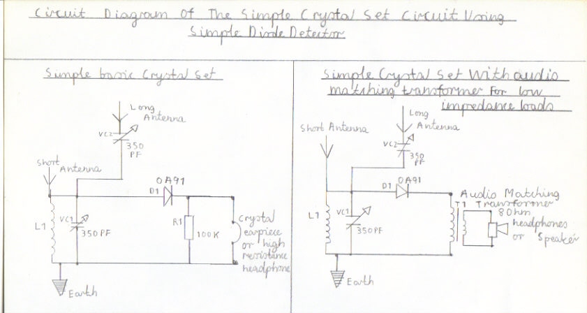

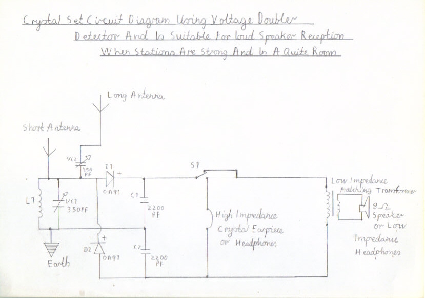

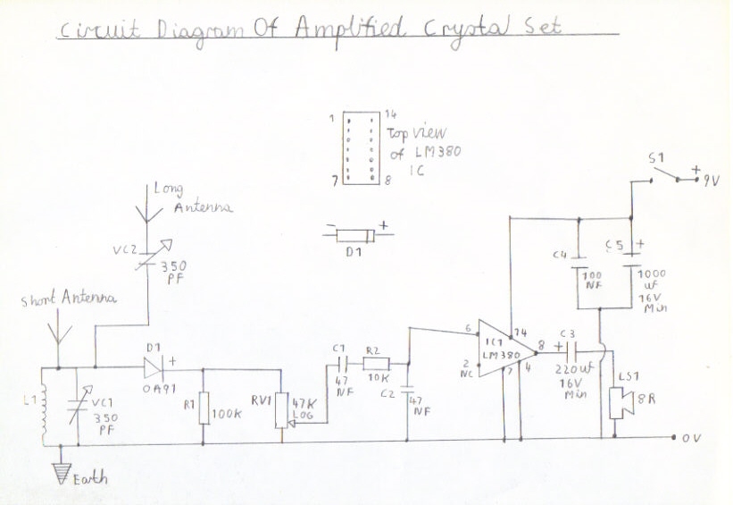
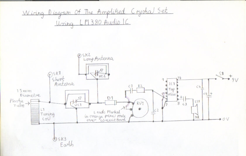
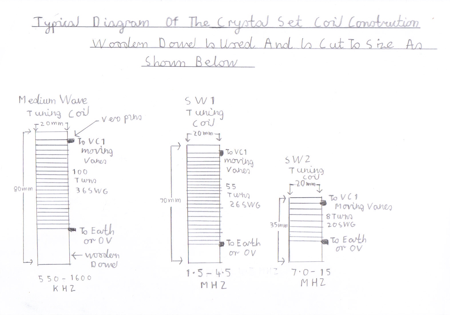
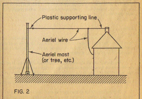
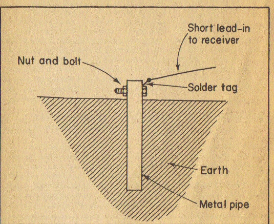

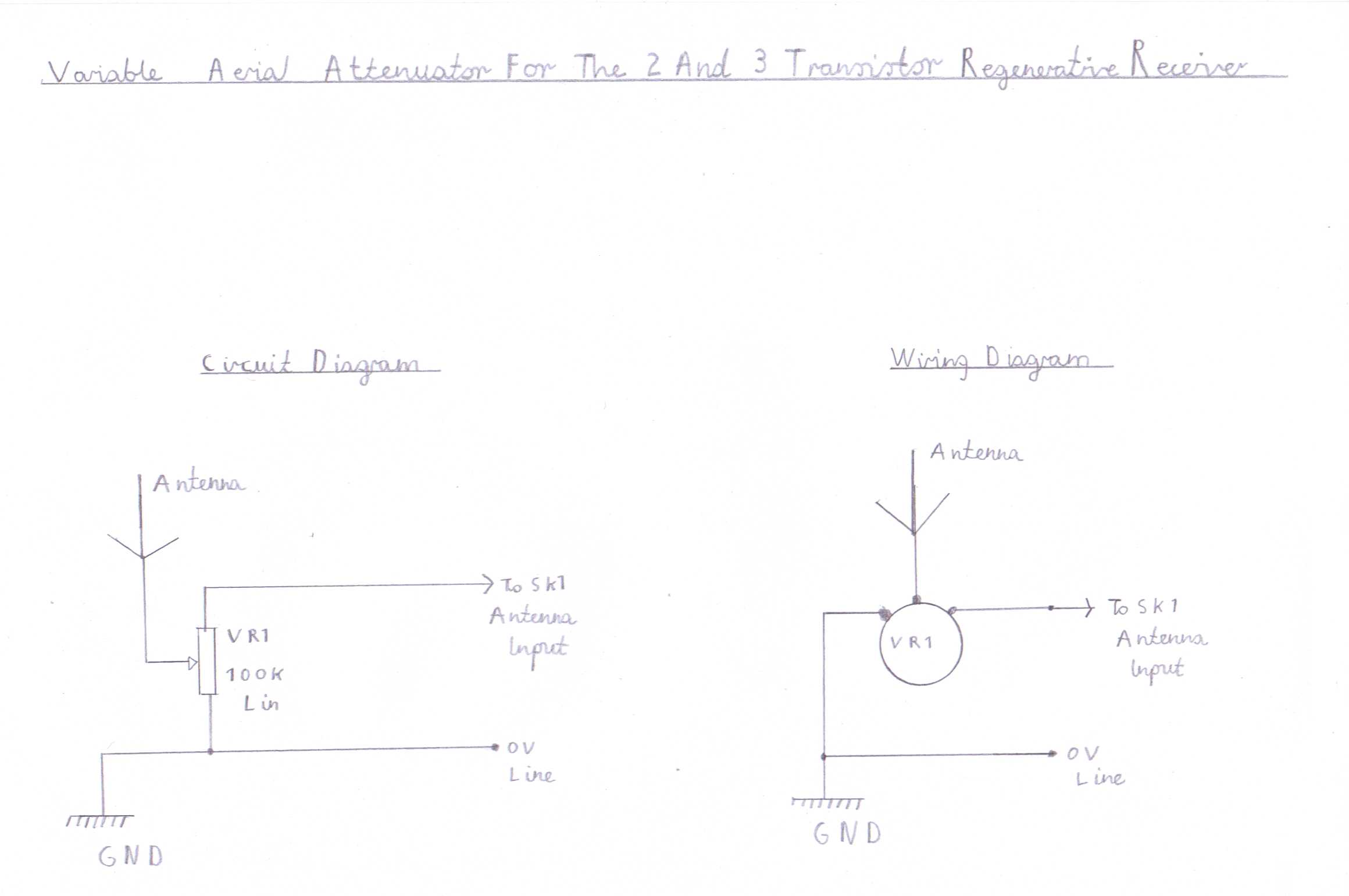
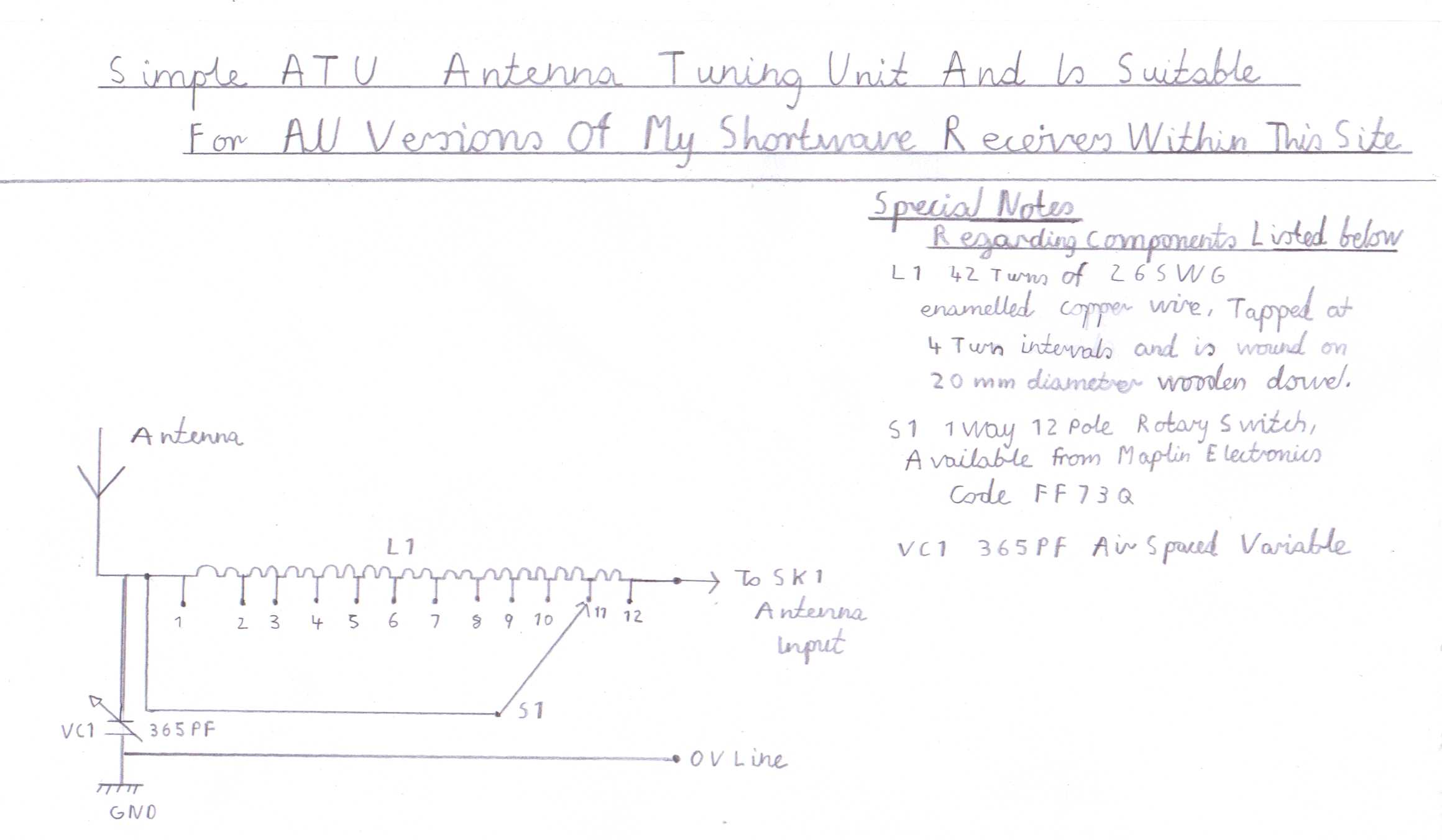
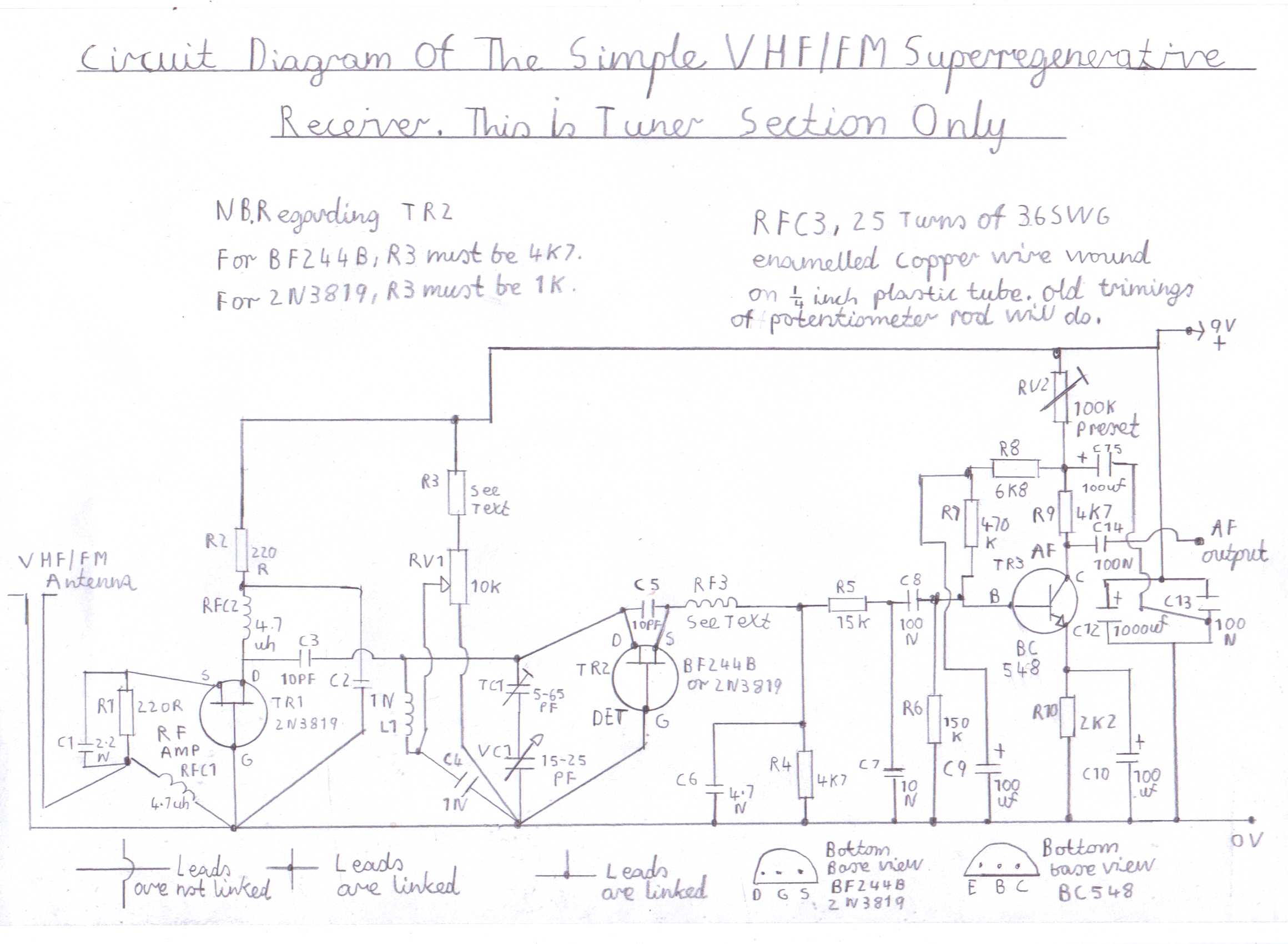


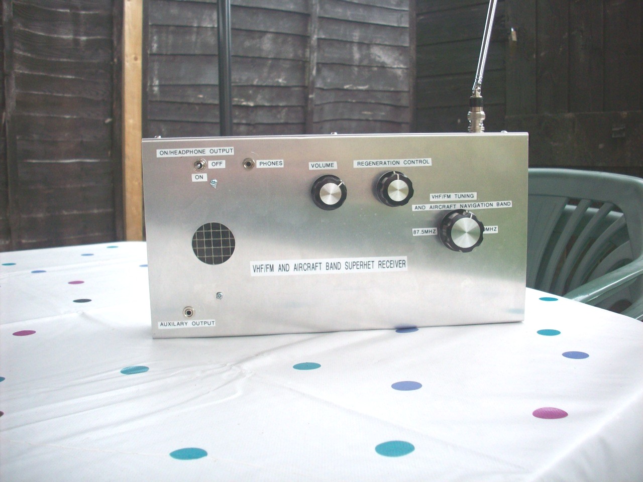

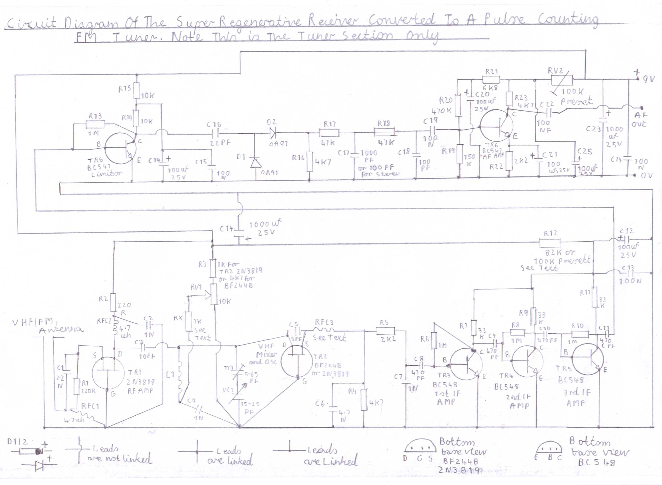
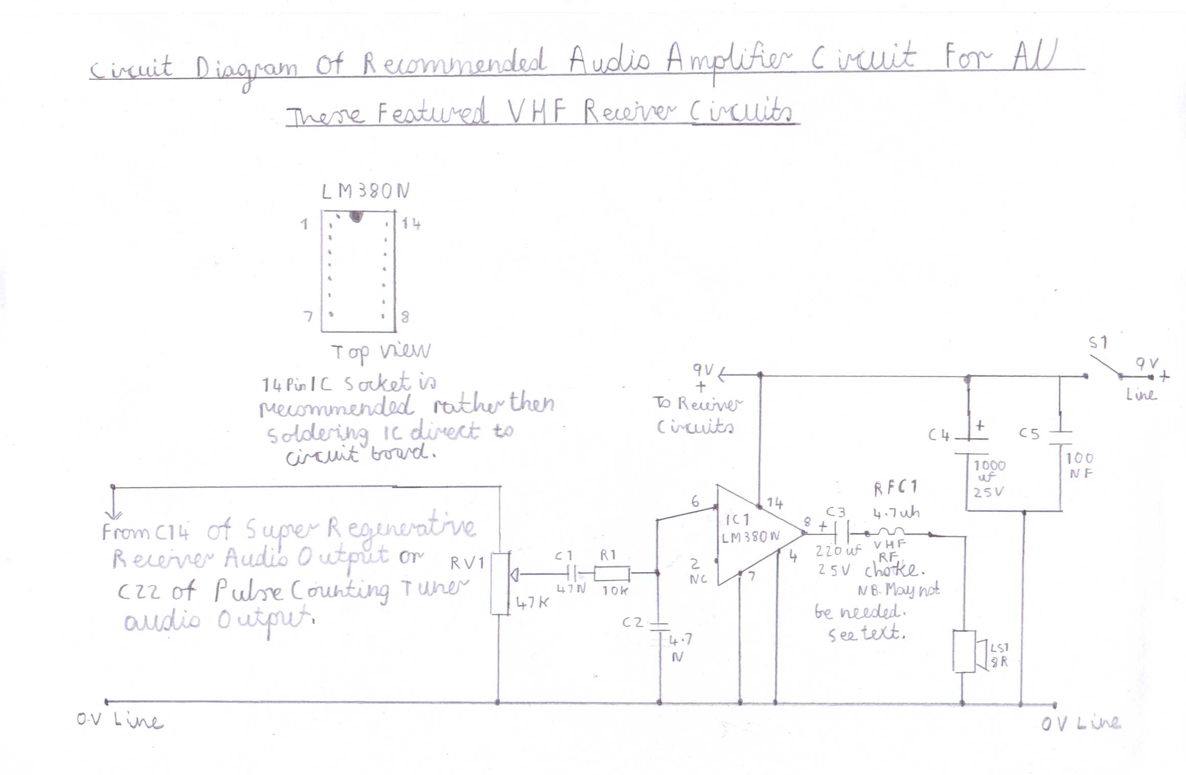
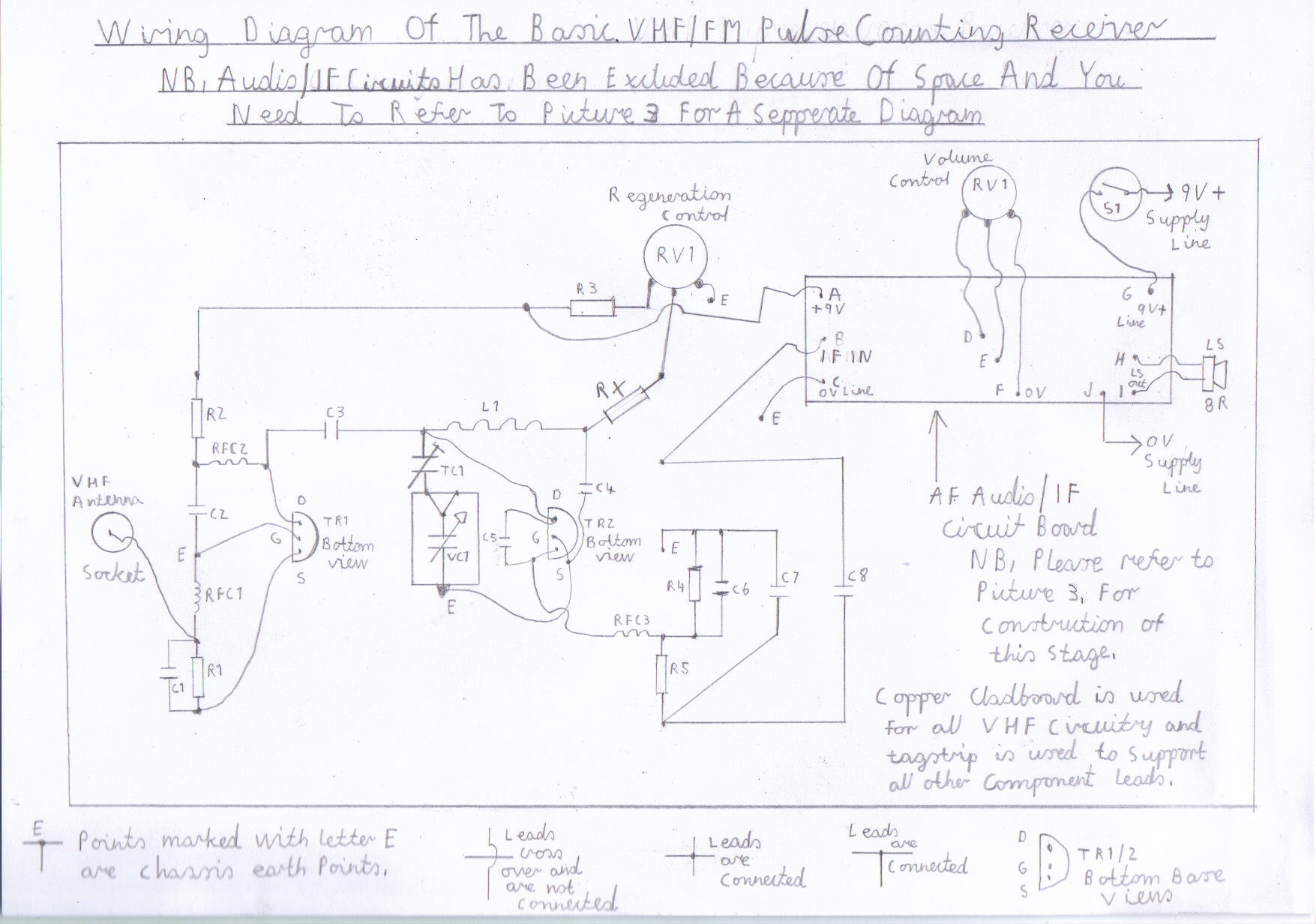
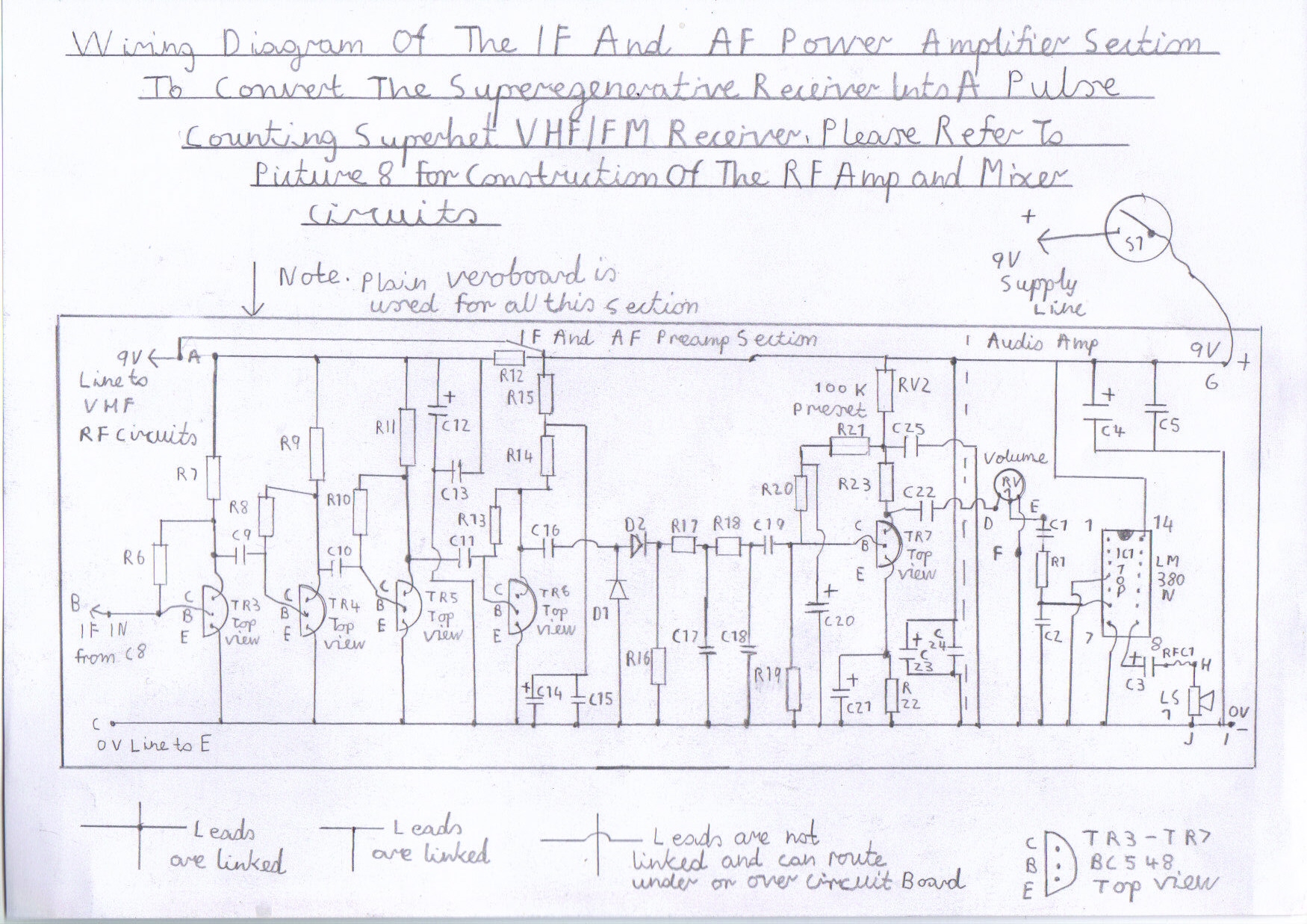
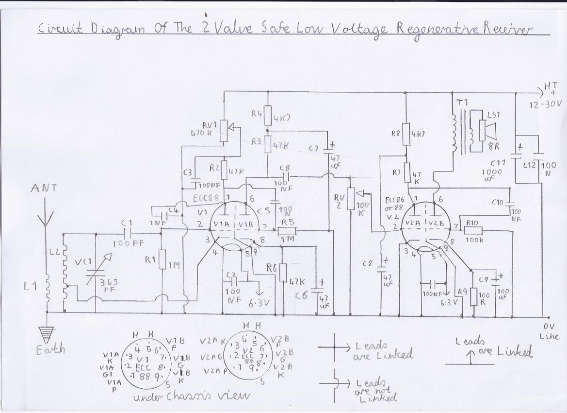
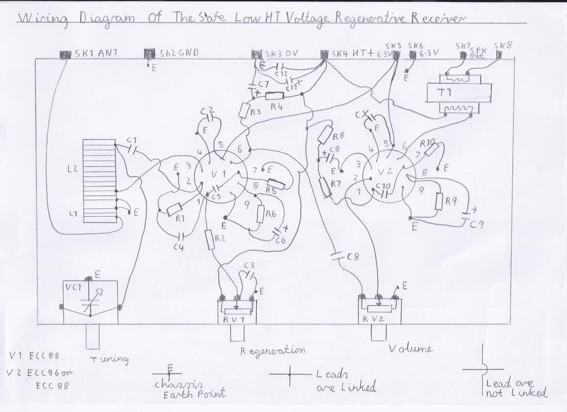

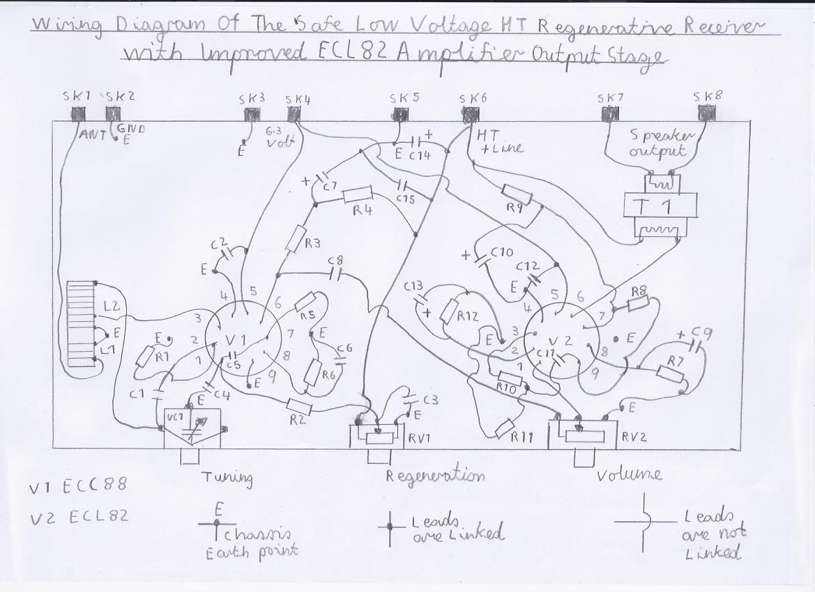
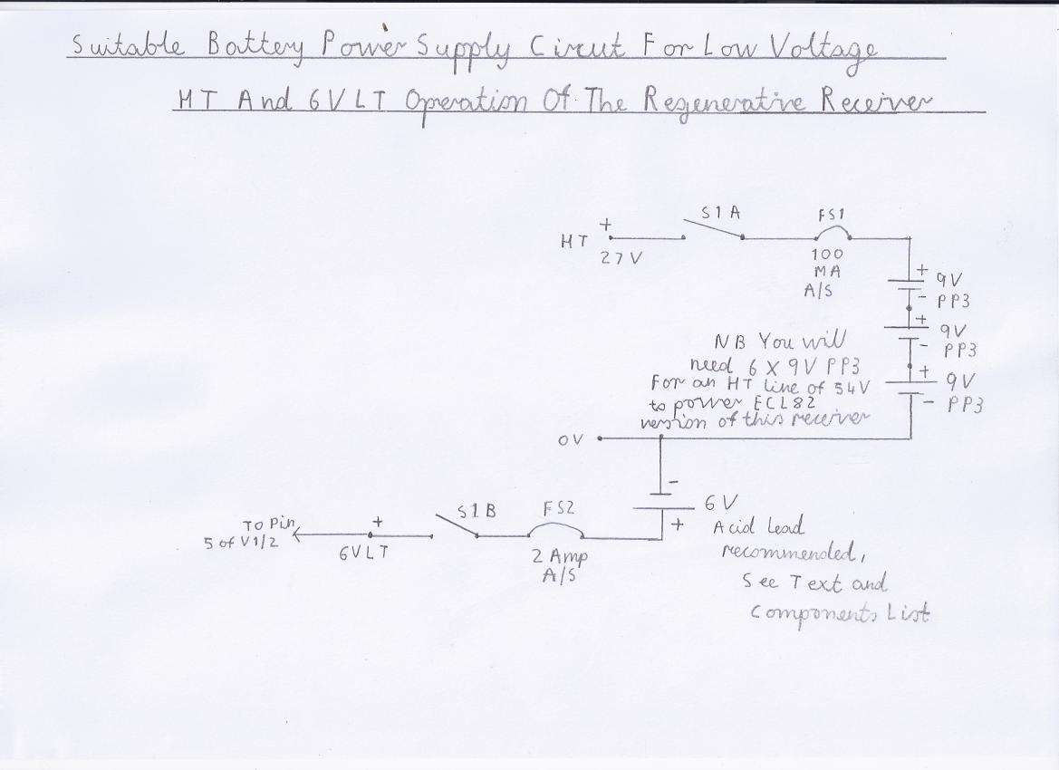
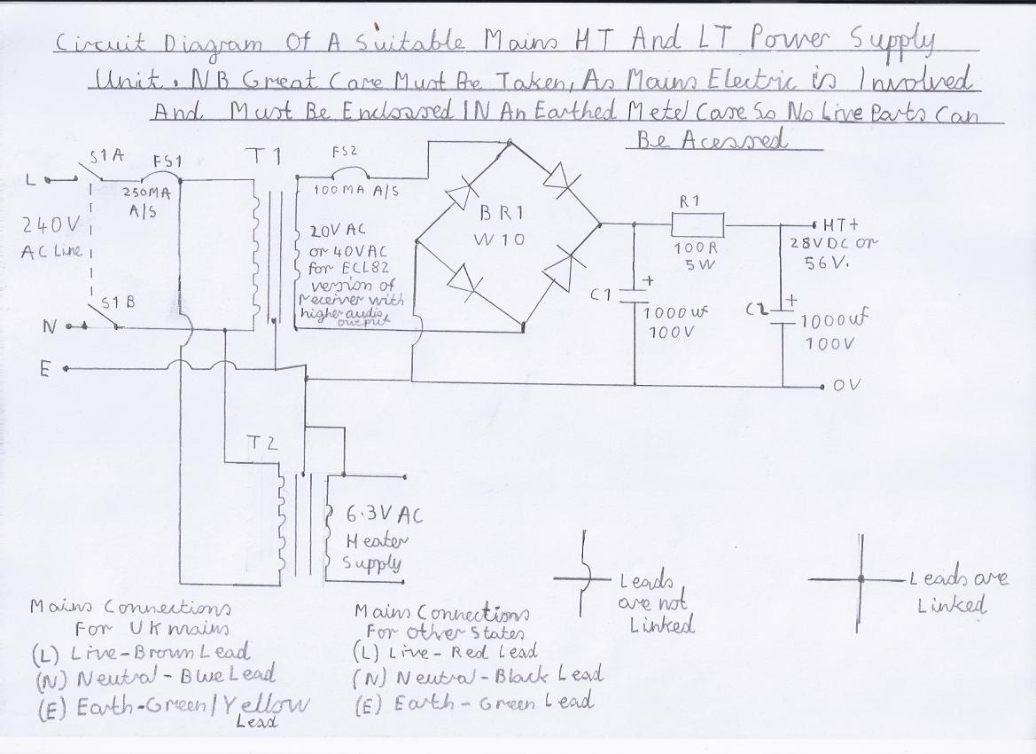
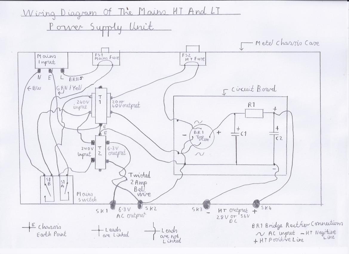
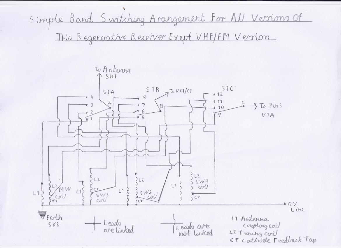


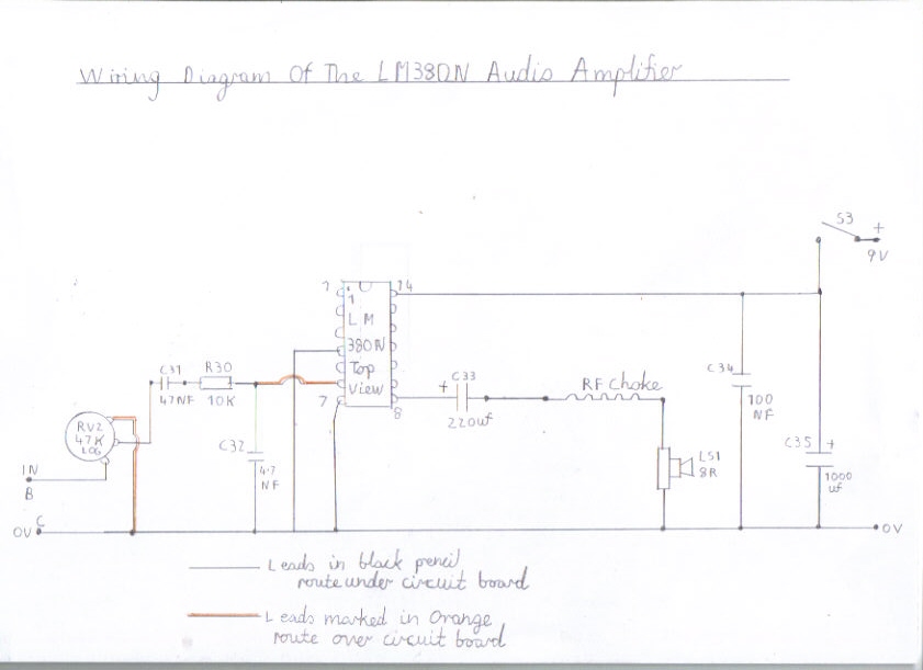