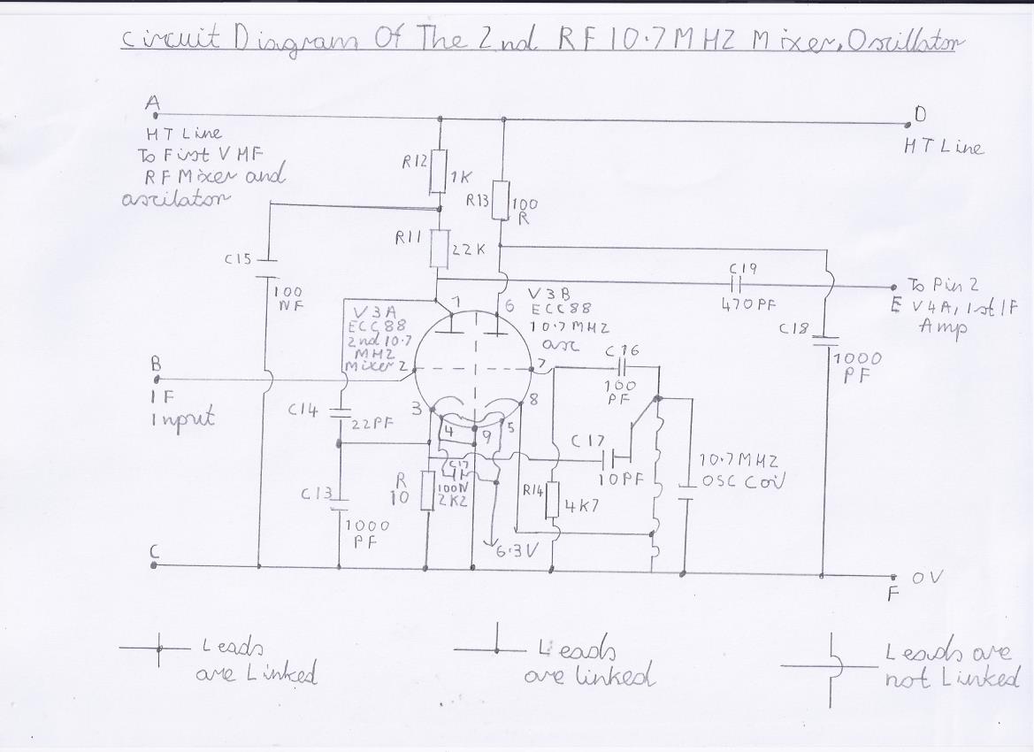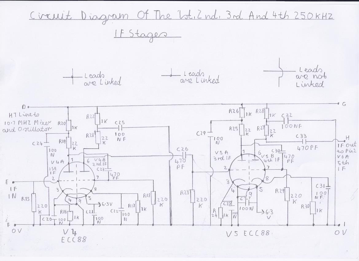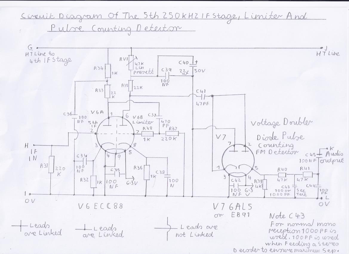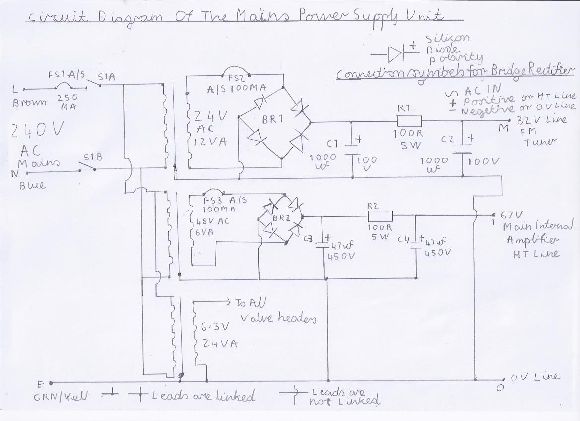
Valve Version Of The 10.7 MHZ Double Conversion VHF/FM Pulse Counting Receiver
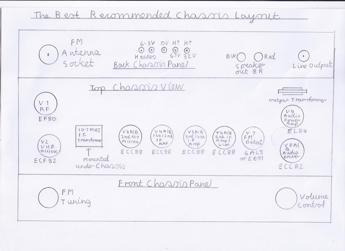
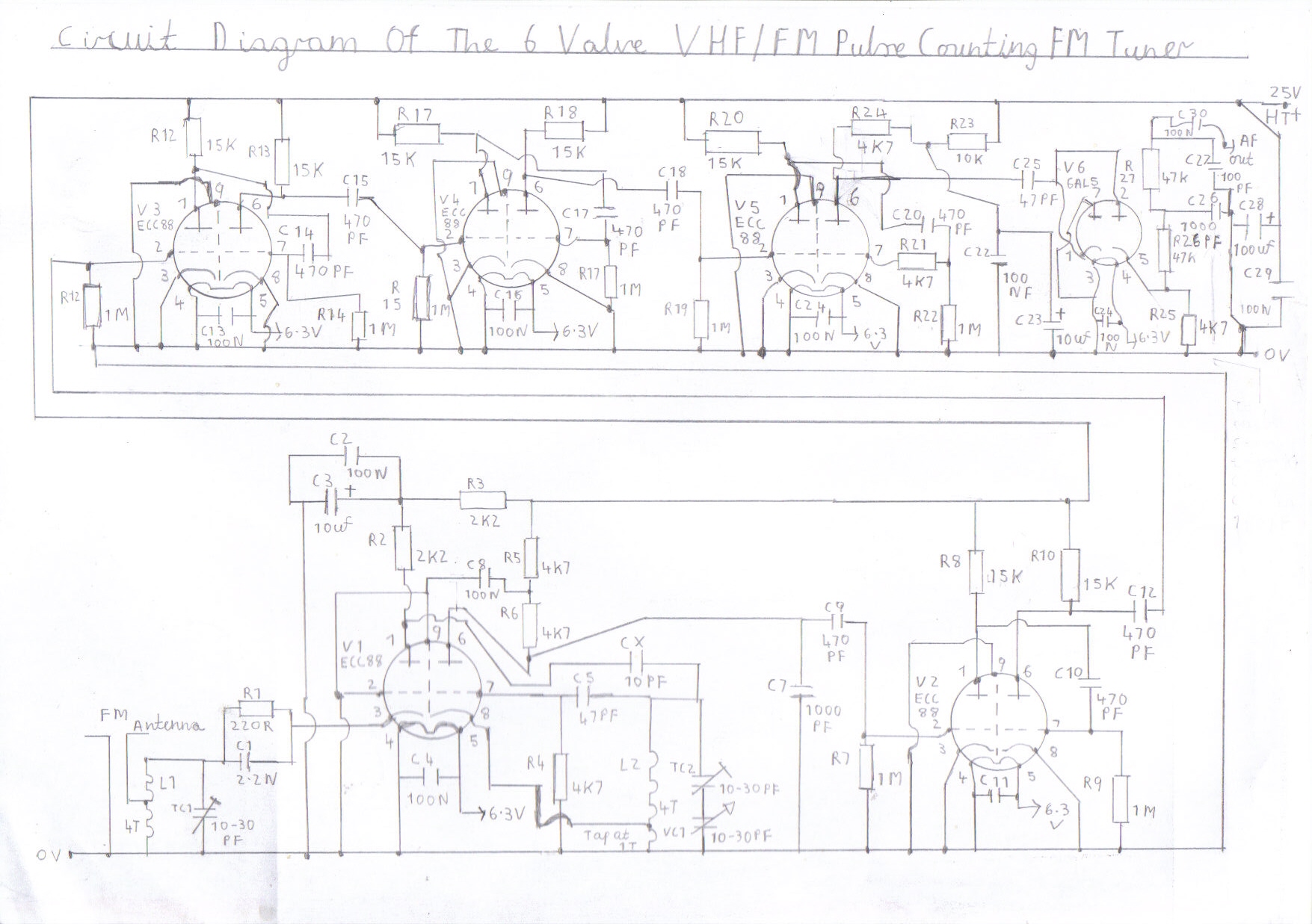
This part of my site features a modified version of my 6 Valve VHF/FM Pulse Counting FM Tuner Using Safe 25Volt DC HT Line . It is of a double conversion type and works in the same way as my solid state Double Conversion Pulse Counting FM Superhet Receiver With 10.7 MHZ First IF Stage except this later design uses valves. As you can see in the following 2 pictures it is a conversion of my original valve pulse counting FM receiver. I want to make a few points clear to anyone for example who may have either stumbled upon this webpage and thought Wow it looks a very encouraging project and think I may like to have a go at building this design myself as a first time FM Receiver project. I will add the first point that if the design is built and aligned correctly, It is capable of very excellent performance and is to this day after doing extensive reception and listening tests I describe it as my best Valve VHF/FM Receiver project. Because it is of the double conversion type there are 5 different tuned circuits to align which makes this version of the receiver much more complicated then the present 6 Valve VHF/FM Pulse Counting FM Tuner Using Safe 25Volt DC HT Line particularly to those of you who have never built a superhet receiver before weather VHF or Medium Wave or does not fully understand how the superhet principle works. As it is an upgrade from that design you should read that article and familiarize yourself with the single conversion design first as the Low Frequency IF and pulse counting detector in this design is basically the same except for a few modifications in the RF Stages. Also the next point I want to make clear is that this is an advanced project and not intended for the first time novice to make an attempt at constructing as it is assumed the experienced valve radio constructer has learned enough experience for me to not include advanced safety precautions except for the safe constructing of the power supply unit and making sure all components such as rectifier diodes and smoothing capacitors are connected with the correct polarity. To add to this latest point regarding safety, An HT line of 32 Volt DC is used along with the 6.3V heater supply which poses less of a electric shock risk then the common 250V HT Line used in commercially built valved audio equipment. Also if you intend constructing the internal EL84 power amplifier stage you will need to include a separate HT supply of 67V DC that needs a bit more care due to the higher voltage involved. Enough now said on this subject and I will now describe what the double conversion superhet receiver is and how it works. The double conversion approach has been popular in many of the more expensive valve communication shortwave receivers and later solid state versions even included a triple conversion which made the design even more complicated. So what is the purpose of a double conversion superhet receiver when the single conversion design works and performs well enough to enjoy as an all entertainment broadcast receiver you may ask. Because the single conversion receiver has its mixer following the IF Amplifier Stages it is possible for the receiver to suffer from second channel interference known as harmonics within the tuning range or double tuning points. Very sensitive shortwave receivers suffer from this problem during the high summer sunspot periods which peak at every 11 year cycle. I will briefly describe the first instance. Suppose for example that Radio Moscow is broadcasting a very strong signal on 7.4 MHZ. It may then be possible to hear the same station on 14.8 MHZ while trying to listen to a weaker station due to the simple fact that you are tuned to the second harmonic. In the second instance for example I happen to be using using a medium wave superhet receiver with an IF Frequency of 455KHZ to receive my local radio station on 760KHZ. 760 + 455 = 1215 KHZ and happens to be the same frequency on which the UKs National ILR Station Absolute Radio is broadcast on. In the case of this instance it is possible for the local oscillator to interfere with a nearby receiver tuned to 1215KHZ which will stamp out this signal if the receiver local oscillator is of poor design. In the 3rd instance if you are near the 1215 KHZ transmitter and the signal is strong enough it is possible for this station to also interfere with the local oscillator which can be head as whistling accompanied with the original intended signal. This can also be a severe problem during the late winter evenings due to the powerful European stations all having to be on air at the same time which was for this reason the VHF/FM Service was introduced to the UK during the mid 1950s for the more serious Hi Fi and classical music listeners. Also a tuned RF Stage is used ahead of the mixer on the middle to high class valved communications receivers to help resolve the later problem but the double conversion approach is even better. Now it is time to describe the working order of this design which I will briefly explain. To make it easier to understand the working principle of this receiver we will ignore the VHF sections for the time being, That is V1 The RF Stage, V2A which is the VHF mixer and V2B the VHF Local Oscillator. V3A is the second RF Mixer and is simply tuned to a Shortwave frequency of 10.7 MHZ and is the standard IF Frequency for FM when building receivers that incorporate the Ratio Detector or Foster Sealy type used in valved and solid state receivers of 50s and 60s era. V3B is the second local Oscillator and is injected into the second RF Mixer with a signal of 10.95 MHZ to down convert the IF signal to 250KHZ. This later method of down converting the signal is required on the lower HF Shortwave Frequencies due to the wider bandwidth compared to the VHF Frequencies and is for this reason the original Autodyne converter used on the single conversion designs is not suitable. You need to refer to picture 2 for circuit information regarding this stage. V4A to V7 is the whole IF chain consisting of a 7 Stage resistance coupled 250KHZ IF Amplifier and amplifies the IF Signal in the same way as the 6 Valve VHF/FM Pulse Counting FM Tuner Using Safe 25Volt DC HT Line so little to be said on this part of the circuitry. You need to refer to pictures 3 and 4 regarding circuit information on these stages. V8A/V8B is the Audio and line driver preamp circuits required for driving the internal Audio and external power amplifier stages and also works in the same way as in the single conversion design. You need to refer to picture 5 for circuit information on this stage. V9 is the optional EL84 Power amplifier stage if you intend having the receiver as an all compact design and not just as an FM Tuner. You need to refer to picture 6 for information regarding this stage. At this stage with all these circuits connected together we simply now have a single conversion fixed frequency shortwave receiver working at 10.7 MHZ which will form as an FM IF Amplifier and Audio stage. In order to receive FM broadcasts in the 88 to 108 MHZ UK FM Standard broadcast band we need to add a second Frequency converter and tuneable oscillator circuit to follow which I will fully describe. V2A is the VHF mixer and again a separate mixer is required for this purpose and consists of the ECF82 Triode Pentode type valve and the pentode is used as the mixer section. The Triode section forms as the VHF local oscillator which is V2B and this valve performs very well at VHF as well as being my favourite valve for low voltage shortwave superhet and regenerative receivers. Like in the single conversion design the V1A Mixer section is simply broadly tuned to about the centre of the FM band which will save the cost of a dual gang tuning capacitor although if one is available it will slightly improve RF sensitivity. In order to down convert the FM signal I will describe the function of the local oscillator which is the triode section of V2B. In the instance of the single conversion FM Receiver we only need to tune the VHF local Oscillator 250KHZ below or above the reception signal frequency and that is why the simple autodyne converter was acceptable making the VHF circuitry very simple and easy to understand. This earlier method will not work with an IF of 10.7 MHZ due to the large difference in the IF frequency so a separate mixer and oscillator must be used. Like as the single conversion design we can have the IF frequency below or above the reception frequency which I will describe the first example. Suppose we want to tune to the low end of the FM band starting at 88 MHZ ? If we are are tuning above the reception frequency then we must make sure the VHF Local Oscillator is tuned to 98.7 MHZ with the tuning capacitor vanes fully closed. In the next instance we want to tune to the high frequency end of the FM band which ends at 108 MHZ ? In this case the VHF Local Oscillator must be tuned to 118.7 MHZ with the tuning capacitor vanes fully open. There may be an instance when having the VHF Local oscillator frequency 10.7 MHZ below the reception frequency may be advisable which I will briefly explain. If you happen to live near a local Airport it may be possible to interfere with aircraft navigation traffic if the local oscillator happens to be not well screened as 108-136 MHZ happens to be the Aircraft Navigation Band. In the case of this later instance, The oscillator frequency must tune between 77.3 to 97.3 MHZ. This is what we now call double conversion and as a result we now have a fully working FM receiver that is sensitive and free from second channel interference. Before I describe the function of the V1 RF Amplifier I will just describe other advantages in using a separate RF Mixer and Oscillator in any AM/FM Receiver design. Firstly you are not applying the brute force of the oscillator signal into the IF stages which results in better stability and as the mixer forms as an RF Stage you archive a bit more sensitivity on the weaker signals making an extra RF Stage unnecessary providing the Local Oscillator is well screened to prevent radiation which can affect the reception of nearby FM listeners who are tuned to the same reception frequency which is unlikely with the the reception signal being 10.7 MHZ above or below the oscillator Frequency which is also another good advantage. Having said in the last statement an extra RF stage is not necessary, Having an RF Stage which is the function of V1 following the mixer not just only results in more extra protection against oscillator radiation, It also results in better sensitivity even with the most mediocre antenna system and makes the receiver more portable as the short telescopic antennas work very well with this design in every location of the house. Also if you happen to have an excellent existing antenna system it is possible to archive better hiss free reception above 60 Decibels which is required for the successful reception of stereo broadcasts. The V1 RF Stage consists of an EF80 Pentode which is another excellent valve for low voltage HT operation as it has a steep slope curve and was originally designed as a TV Video IF Valve. Like with the V2A Mixer circuit this stage is a tuned RF Amplifier and is broadly tuned to the centre of the FM Band for maximum signal reception. At this point we now have archived a double conversion pulse counting FM Tuner capable of excellent performance. Constructors who have built the 6 Valve VHF/FM Pulse Counting FM Tuner Using Safe 25Volt DC HT Line may convert that design to this later version providing there is plenty of space on the chassis where the VHF front end RF components are located and space is not crammed up. Picture 9 is also the new recommended layout diagram for this latest configuration if you intend building from scratch.
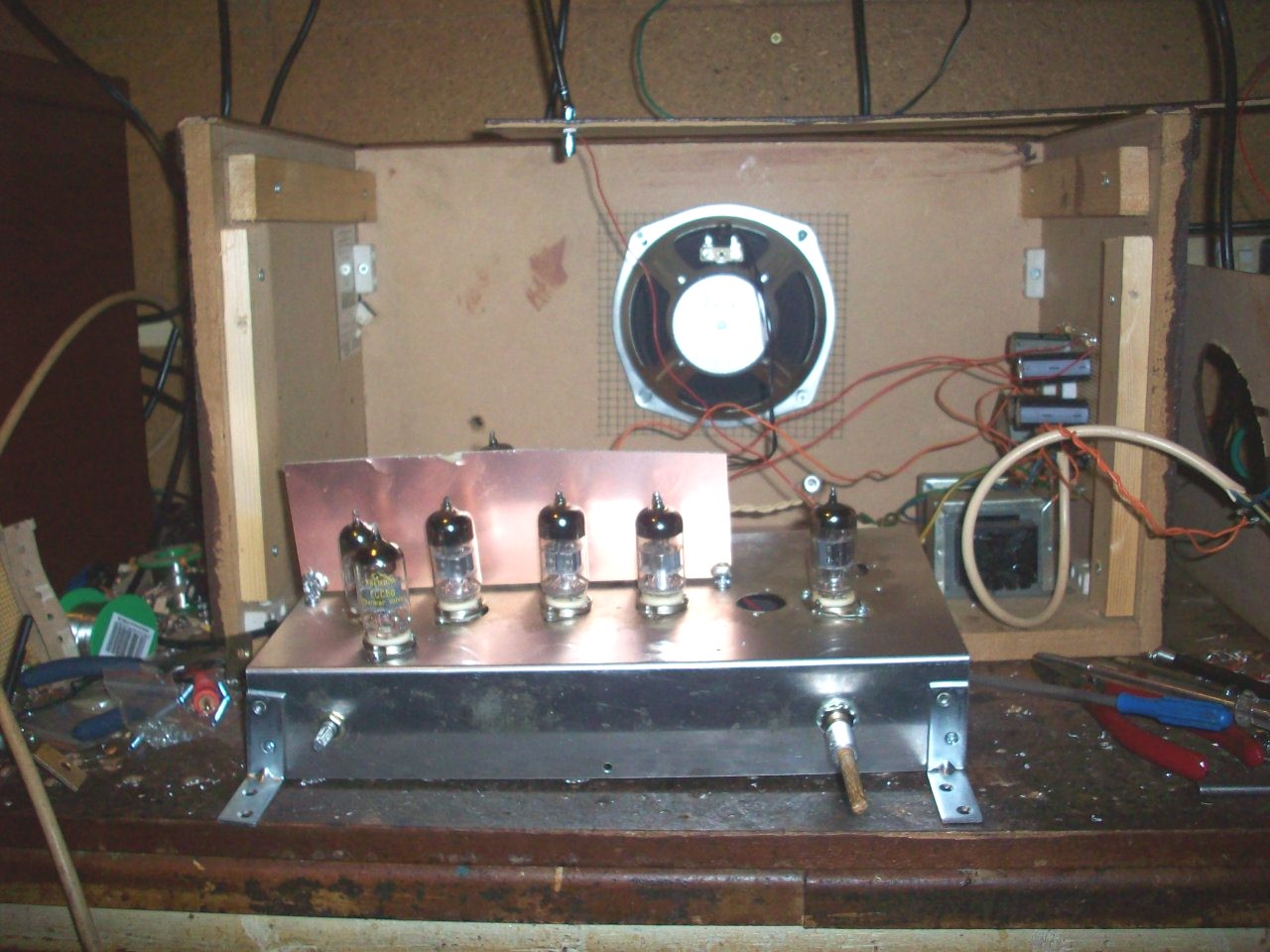
Top chassis view of the Valve Double Conversion FM Pulse Counting Receiver. Note that an RF laminated copper shield is used to screen the audio and IF valves as instability was an issue on earlier and this later version of this receiver. Please refer to picture 9 for an updated layout diagram of the chassis layout.
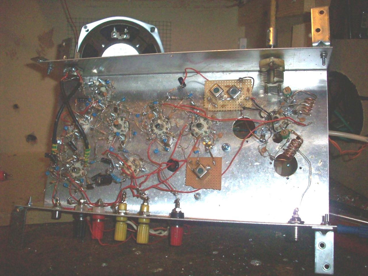
Under Chassis View Of The Valve Version Of This Double Conversion FM Receiver
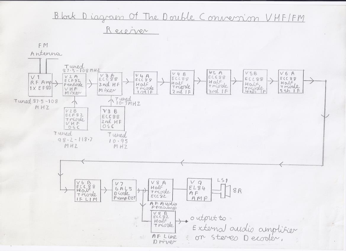
Block Diagram Of The Valve Version Of Double Conversion FM Pulse Counting Receiver
|
|
|
|
|
|
|
|
|
|
Please left click on selected picture to enlarge image.
Construction Details Of This Receiver
Has it has been already said in the introduction text, This receiver is an upgrade of 6 Valve VHF/FM Pulse Counting FM Tuner Using Safe 25Volt DC HT Line and you must read that article first before going ahead with the construction of this more advanced version of the Valve Pulse Counting FM Receiver. As A4 Printer and scan paper is so small there is no way that a single circuit diagram of the whole receiver can be composed on one sheet so all diagrams have been composed into building blocks and the connection points on each stage use an alphabetical identification system to help matters more. Also the safety precautions regarding the safe constructing of this receiver are very much the same as for the earlier single conversion design and I am going to just make these final points clear on this subject as only aligning up the RF stages will be mentioned in the final text. Although this valve receiver uses a safe 32V HT Line this project is not suitable for any one who has never built a mains powered project before as it still involves the use of 240V AC on the mains input. Also this version of the valve FM tuner uses more RF complex circuitry in the VHF circuits so this is the second reason newcomers to radio construction should not attempt to build this version of the valve FM receiver. I will briefly describe the levels of skill required to those who may feel tempted to build it from scratch. This project is suitable for anyone who has constructed my following superhet receiver projects in random order. Introducing Superhet Receivers' Featuring Add On Converter For The Two Valve TRF Receiver in which that version of the Frequency Changer uses similar technology regarding the front end. Also the Severn Valve HF Superhet Receiver Designed For Advanced Constructors uses the same front end technology and is therefore suitable. Finally if you have successfully built the Double Conversion Pulse Counting FM Superhet Receiver With 10.7 MHZ First IF Stage the RF alignment procedure is exactly the same except like I mentioned previously it involves the use of 240V AC mains so great care is needed on this side of things if you have had no experience of building mains powered valve equipment. I hope you now understand these points clear and if this is so I will describe on how to go about the testing and the final alignment in the 3rd section of this article. I will also describe on how to convert the 6 Valve VHF/FM Pulse Counting FM Tuner Using Safe 25Volt DC HT Line in the final write up of this article. Picture 8 is the new chassis layout diagram of this design and can be built on the same size chassis as the single conversion design unless you want to include all power supply components on the same chassis. NB If you are building the receiver in the same order as the new layout diagram then the copper shielding between the IF and EL84 output valve is unnecessary which was a cause of AF instability in the Single Conversion Design. You must make sure that all wiring particularly in the VHF RF Stages are short and direct as possible or tuning drift and lack of frequency coverage on the high frequency end of the FM Band may occur. Another note regarding the construction of the VHF RF stages. These stages must be wired up and tested last as the 10.7 MHZ RF alignment must be carried out first before the 32V HT line can be connected to the primary of the 10.7 MHZ IF transformer. Because this version of the Valve FM Tuner is intended for advanced constructors I have decided that compiling a full components list can be time consuming and instead I have highlighted a list of component suppliers in the next heading of this article.
Component Availability
Most of the components such as resistors and capacitors should be easily available from UK component suppliers such as Maplin Electronics or Cricklewood Electronics CCTV and Electronic Components which sells other items such as the valves, Valve Bases and Transformers. The most hard to get items are the Tuning Capacitors and 10.7 MHZ IF Transformers. The following link Mainline Electronics does still manufacture the popular Jackson Variable Capacitors except they have no online shopping facilities so it means telephone conformation and ordering by post. 25PF is the recommended minimum value if you intend to archive maximum coverage of the entire FM Band particularly the low frequency end of the band with no dead ends. Valve type 10.7 MHZ IF Transformers are very hard to come by unless you happen to have an old valve radio with VHF/FM that you want to part with but on the brighter side of things transistor type IF transformers can be made to work by using the following method. You need to refer to picture 8 which shows and explains how to couple 2 of them with there low impedance windings connected back to back. You must also make sure when coupling these IF Transformers that you also use the 2 100PF ceramic capacitors as shown in the diagram because these are wound with very fine wire and it has been known with HT voltages as low as 25V to leak through the insulation and burn out the windings. You will need 2 of them and the following component supplier Mouser Electronics - Electronic Components Distributor has these in stock and the order number is 42IF123-RC also the following PDF file is showing the connection details is available from the following link http://www.mouser.com/ds/2/449/XC-600131-205883.pdf . The following link Watford Valves has all the availability of the valves for this receiver at reasonable prices. Also my following link How To Get Components shows all the component suppliers. NB Note regarding the oscillator coil used in the 10.7 MHZ 2nd local oscillator. You will need an extra 10.7 MHZ IF transformer to make this coil up and this particular component is the same type and order number as the ones used for the 10.7 MHZ RF Second mixer so in all you need a total of 3 transistor type IF Transformers.
Final Testing And Aligning This Receiver
This is where all the fun and excitement starts but I will give you 1 last reminder before proceeding. You must double check to make sure all wiring in the mains power supply unit is correct before throwing the switch because simple mistakes can be costly and even very dangerous. In particular you must check that all electrolytic capacitors both in the receiver and smoothing circuits are of the correct polarity and that also includes the bridge rectifier. If the correct mains and HT fuses are present then the damage will be limited but it is advisable to stand at least 2 metres clear before switching on the mains for the first time and if you see any sign of smoke or smell burning then switch off immediately and recheck your wiring. This Receiver is tested in the following sequence which I will fully describe.
1. Insert the EL84 Output Valve V9 If you have included the power amplifier and insure that suitable 8 Ohm Speaker is connected before switching on the power. If you have not included the power amplifier then ignore this and proceed to step 2.
2. Insert the ECC82 Audio preamplifier valve V8. Switch on the power and allow about 1 minute for the valves to warm up to maximum operating temperature.
3. Advance the VR1 Volume control fully clockwise. With a screwdriver blade, Touch point K the signal grid input of V1A and if all is well a high pitched audible buzz should be heard which means everything is working ok at this stage. If you intend using an external audio amplifier proceed to step 3.
4. Weather you have built the audio power amplifier or not, This tuner can be used to feed any audio amplifier and Hi Fi Mono can be a archived at excellent audio quality. The take off point is at V8A point N and if connecting to any valve power amplifier you must ensure the C30 anode coupling capacitor is rated at 500V minimum or preferably 1000V if feeding to high powered valve amplifiers such as the Mullard 5-20. Do not attempt to connect this Tuner to any valve amplifier or receiver that is of the AC/DC Type which is designed for Universal Mains which in that case does not contain a mains isolating transformer or the chassis may be live and a serious electric shock hazard may exist. If you have not built the audio power amplifier you will need to refer to picture 5 and make sure the heater of pin 5 is not connected or cathode poisoning of V8B will result due to no cathode emission. If you have built the audio power amplifier you need to refer to picture 6 for circuit information and you must ensure the pin 5 heater 0f V8B is connected. Please also note that the circuit is wired so that when you have the receiver volume control set to any desired level, The audio level from the output take off point N is not affected. If all is well with testing and setting up these stages you may now proceed to testing the low frequency 250 KHZ IF Amplifier stages which will be described next.
5. Insert the V6 ECC88 5th IF/Limiter Valve followed by the V7 6AL5/EB91 Pulse counting discriminator valve. Allow at least 1 minute for the valves to warm up to maximum operating temperature.
6. Try lightly touching your finger on Point H which is the IF input at V6A Pin 2 control grid and if all is well you should hear high pitched rushing and a few stations such as Radio 5 Live UK cluttered together with other stations within the medium and long wave bands due to the wide bandwidth. If this is so this also means this part of the circuit is working and you may proceed to the next step.
7. Insert the V4 and V5 ECC88 Valves which form the 1st 2nd 3rd and 4th IF Stages. Allow at least 1 minute for the valves to reach maximum temperature.
8. If all is well the receiver should now sound very alive with a very high pitched hiss and touching point E which is the 1st IF input at the V4A Pin 2 control grid should produce the same results as in step 6 except with more lively results. If this is so then everything regarding these stages should now be ok and you may now proceed to the next step which is aligning the second 10.7 MHZ mixer and oscillator which will follow next.
9. You need to refer to picture 8 for the layout diagram of the 10.7 MHZ IF Transformer configuration. As I presume you have not built the VHF section yet please follow this step carefully. On a temporary basis you need to strap 1 side of the primary section of the IF Transformer to ground preferably the side that says to pin 6 Pentode Anode V2. Insert V3 which is the 10.7 MHZ Frequency Changer and local oscillator valve. This stage can be tuned by ear but if an RF signal generator is at hand it will speed the job up and allow more precise alignment. Please refer to the next step if using an RF signal generator.
10. Strap the black RF signal generator probe to point C or any 0V potential point of the receiver chassis. Next connect the red probe to the other side of the IF Transformer Primary which will later connect to the HT supply at Junction with R7 C8/9.
11. Reconnect the receiver and allow over 2 minuits for the valves to reach maximum full working temperature. You next need to set up your RF signal generator as follows. Set the modulation to tone and tune the signal generator around the 10.7 MHZ portion until you hear a tone signal. If this is the case then you next need to adjust the IF transformer cores for maximum signal strength. If all these steps have been successful then please proceed to the next step which is setting the tuning precisely which is one advantage of having the luxury of a signal generator for aligning any superhet receiver.
12. Most and particularly older signal generators have 10.7 MHZ and 455 KHZ markers which are intended for precise alignment of superhet receivers. To correct this you will need to slowly retune the 10.7 MHZ Oscillator coil and signal generator until you can get the tone signal dead on the marker. Advancing the core of the oscillator coil in the anticlockwise direction swings the 10.7 MHZ IF Signal in the high frequency direction while maintaining the core in the clockwise direction lowers the 10.7 IF signal tuning in the low frequency direction. You will also have to Keep repeaking the IF Transformer for maximum signal strength. Also if your signal generator incorporates a variable attenuator try to maintain this control as low as possible to avoid misleading results. If you do not happen to have an RF Signal generator to hand there is an alternative and not the best by professional standard way of aligning this type of receiver which is one of the main reasons that newcomers attempting to have a go at building this design is not by all accounts recommended. To align the 10.7 Mixer and Oscillator stages using this later method please refer to the next step.
13. Connect about 1 metre of tinned copper wire to the hot side of the IF Transformer primary preferably the side that says To R7 at Junction with C8/9 HT Line to form as a temporary antenna. You also need to connect the side to any 0V point for the time being.
14. Insert V3 which is the 10.7 MHZ Frequency changer and local oscillator valve. Reconnect the receiver and allow the valves about 2 minuits for the valves to reach working temperature.
15. At this point now the receiver is working as a single conversion shortwave superhet receiver and if all is well you should hear shortwave activity such as stations broadcasting near the 10.7 MHZ IF frequency or other high pitched pulse noises. If this is the case then you need to keep peaking the IF Transformers for maximum signal strength.
16. If all these steps at this point have gone to plan then the construction of the VHF RF circuitry can go ahead which will complete this project. Before I describe the construction and setting up of the VHF circuitry I will just briefly explain on how the 6 Valve VHF/FM Pulse Counting FM Tuner Using Safe 25Volt DC HT Line can be adapted to this double conversion design. Please refer to these next 2 steps for more details. If you are not intending to convert the original single conversion design then simply ignore these next 2 steps and proceed to the constructing and setting up of the VHF RF Stages.
17. Please note that there must be enough room in the main chassis so everything is not to crammed up and as a final reminder if your experience in understanding how this later receiver works has not sunk in to you then do not even think of attempting this modification. If you are confidant in attempting the conversion then please refer to the picture below which is the original single conversion circuit diagram.
|
||||
18. Referring to the above picture of the single conversion valve FM receiver please note the following stages that will need to be modified. All VHF circuitry of V1A and V1B will have to be removed. The RF coils and tuning capacitors will be ok for the new design except they will need to be rewired into the new VHF RF circuitry. The heater wiring is unchanged and must be retained. Also the circuitry of the V2A and V2B 1st and second IF stages needs to be removed and V2A/B will become the 2nd 10.7 MHZ RF Mixer and local oscillator circuitry. That is about all there is to it except If you are incorporating the new RF Stage which is highly recommended then you will need to drill another cutout for this additional valve.
19. The construction and setting up of the VHF RF Stages will be described next.
Constructing And Setting Up The VHF RF Stages
You need to refer to picture 1 which is the complete circuit diagram of all the VHF RF circuitry. This is where the greatest of care is needed regarding your wiring skills as any long lengths of leads particularly in the VHF Local Oscillator tuned circuits can lead to excessive tuning drift and in some cases the receiver not working at all. The RF coils are wound in the same way as the original single conversion receiver except you need 2 additional RF coils for the VHF Mixer and 1 for the RF Amplifier if included. Also the VHF circuitry needs to be tested and aligned first before the alignment of the RF Amplifier stages can go ahead. The RF coils are self supporting consisting of bare copper wire and are made from the copper strands of 2.5 mm UK Ring mains cable. A useful tool such as an AA Size penlite battery is used to assist you in winding these coils. L1 and L2 consist of about 5 Turns and the windings are spaced at about 1 to 2 mm. L1 is centre tapped although this may require a bit of experimentation regarding on the type of VHF antenna used. Also if the RF Amp stage is not used then you may have to centre tap L2 to match the required type of VHF antenna. The L3 VHF Local oscillator coil needs the following amount of turns in which I will briefly explain. If you have the local oscillator tracking on the high side of the desired reception frequency which is between 98.7 to 118.7 MHZ then L3 must consist of about 3 to 4 turns with the cathode tap at about 1.5 turns from the earthy side of L3. If you wish to have the local oscillator tracking on the low side of the reception frequency that is between 77.3 to 97.3 MHZ then L3 must be wound with about 6 turns with the cathode tap at about 2.5 turns from the earthy side of L3. One note regarding C4 the RF Amplifier coupling capacitor. As the VHF Mixer circuitry must be aligned and tested first you must make sure on a temporary basis that this capacitor is disconnected from the hot side of the L2 Mixer RF coil or misleading alignment results may occur. On a closing note regarding the construction I will just explain a bit more detail regarding the CX Local Oscillator/ Mixer injection capacitor. 10PF is the maximum value and if possible having this value as low as 2PF is preferable and using insulated tinned copper wire lightly twisted together also gives good results. The testing and alignment of the VHF Mixer and local oscillator will follow next which should be the moment of truth.
1. For the time being connect a short length of tinned copper wire say of about half a metre to the L2 mixer coil preferably centre tapped from the earthy to hot side of L2 to form a temporary antenna.
2. Insert V2 which is the ECF82 VHF Mixer and local oscillator valve.
3. Reconnect the receiver to the mains and allow about 2 minuits for the valves to reach maximum working temperature.
4. Try rocking the main VHF tuning capacitor VC1 and it may be possible to tune in at least a few of the high powered local and National stations. If this is the case then try peaking the TC2 Mixer trimmer for maximum signal strength. Also depending on the location of the VHF transmission you are receiving you may need to move the antenna in different directions to achieve maximum signal strength.
5. If all these 4 previous steps have gone to plan and you are not intending on using the RF stage we now have a fully working FM Receiver. Before we can put the receiver into full working use there are 2 important alignment procedures that must be carried out in which first is the final 10.7 MHZ IF Alignment and then correcting the minimum and maximum frequency coverage of the FM Band which will be described next.
6. Try repeaking both of the 10.7 MHZ IF Transformers very carefully and you may find there should be a further improvement in FM Signal strength. If this is the case then we can now go ahead with correcting the FM tuning frequency range which will be described next.
7. The TC3 Trimmer in series with the main VHF tuning capacitor is the oscillator trimmer and its function is used for correcting the frequency coverage of the FM tuning range which I will briefly explain. Lowering the capacitance of TC3, That is with its vanes fully open also effectively lowers the value of VC1 which swings the receiver tuning coverage in the high frequency direction. The reverse is true if the vanes of TC3 are fully closed which in this case you are increasing the capacitance of VC1 and therefore you are swinging the receiver frequency coverage in the low frequency direction. If you now fully understand everything regarding this simple explanation we can now go ahead with setting the correct frequency coverage of this receiver which will be explained next.
8. For example the UK National station BBC Radio 2 is broadcasted on the low frequency end of the FM Band between 88 to 91 MHZ. If you happen to be receiving this station with the VC1 tuning capacitor vanes set at about half capacitance then this needs to be corrected in which I will fully describe. You will need to keep slowly opening the vanes of TC3 and maintain the adjustment of the tuning capacitor until you are receiving Radio 2 with the tuning capacitor vanes just about 4 millimetres open. Before I go any further with this instruction I need to make the following statement. Because this is a double conversion receiver you may find that you are receiving all the same stations again as you tune from the middle to the high frequency end of the FM Band. If this is the case I will briefly explain and tell you how to correct this situation. In the simple case of the full or part of the FM tuning range starting again when VC1 is advanced over half way is very simple. When you start off tuning the FM Band from the low frequency end with the VC1 vanes closed you will be tracking on the low side of the reception frequency. In this case you need to retune VC1 in the high frequency direction until you receive BBC Radio 2 again. In this case you will now be tracking on the high side of the reception frequency which is what we want and you will need to repeat this same step again to correct this situation.
9. If all the above steps have gone to plan then the FM tuning alignment is correct but to ensure that you are getting maximum performance regarding sensitivity then the VHF mixer alignment needs correcting which will be described next.
10. Try tuning into some of the weaker stations on about the mid to high end of the FM band. Re adjust the TC2 Mixer trimmer until maximum signal strength is archived. Keep repeating this step several times on the entire FM band until no further improvement can be obtained and all stations are at equal strength
11. If you are not including the RF stage this now completes the alignment and setting up of this receiver. Before I give advice on the best antenna system for this receiver and the possibility of FM Stereo reception which will close this article we need to go through the setting up of the RF Amplifier stage if you have included it which will follow next
12. Disconnect the temporary antenna from the L2 Mixer coil and reconnect the C3 RF Coupling capacitor to the hot side of the L2 Mixer coil.
13. Reconnect the temporary antenna to the L1 RF coil in the same way as you did for the L2 RF Mixer coil
14. Insert the V1 EF80 RF AMP Valve.
15. Reconnect the receiver to the mains and allow about 2 minuits for the valves to reach full temperature.
16. Regarding alignment, Repeat the same step as you did for the RF Mixer alignment until no further improvement can be archived.
17. If all has gone to plan we now have a fully working Double Conversion Valve VHF/FM Receiver capable of excellent performance. Before I close this article I will explain the best advice regarding the use of FM antennas and the possibility of enabling stereo reception.
Using The Best FM Antenna System And The Possibility Of FM Stereo Reception
No matter how good your FM Receiver is, A poor antenna system can make any receiver useless regarding performance unless you live in the best reception area which would be Holm Moss near Huddersfield or the middle of London where they are plenty of Pirate Radio Stations to choose from. The outdoor Yagi Antennas are certainly the best to go for and must be mounted as high as possible to get maximum performance. The only disadvantage is that they are directional and need to be pointing in the direction of the intended signal if they are to work well regarding performance. If you are intending to have the receiver portable then the telescopic antenna is about the best choice but try get one with a directional swivel as FM Transmitters sometimes have there antenna masts at Horizontal H Polarisation or Vertical V Polarisation. Also indoor Combined FM/TV antennas should work well with this receiver but avoid the ones with the built in aerial preamplifier particularly if you are using the RF stage or front end overload may occur. The last type of antenna to use is the omidirectional type which I will briefly explain. This type of antenna picks up signals in all directions and as a result you may experience multipath signal distortion and interference such as receiving 2 transmissions on the same frequency particularly if it is mounted up high and clear of buildings. I want to make one more point clear regarding the antenna coupling arrangement when using outdoor and indoor antennas that form a complete low resistance circuit. The leaky grid bias resistor arrangement of both the RF Mixer and RF Stage happens to be at the earthy end of the RF Coil and as a result this may short out these components upsetting the biasing conditions of ether valve. To avoid this problem the hot side or centre braid of the antenna must be connected through a capacitor of about 2-10PF maximum value. The last and final issue on this receiver is can it work in stereo. The answer is yes if you happen to live in a good reception area and you have a very good antenna system. Please note that stereo reception needs a good signal of about 60 Decibels or more the better to avoid excessive back ground hiss caused by the 19 KHZ Pilot Tone and the 38 KHZ Subcarrier signal. You will need a suitable Decoder and phase correction circuit which can be found at the following link FM Stereo Decoder Circuit . There is also one slight modification required in the capacitor smoothing network of the Pulse Counting Detector which I will briefly explain. In order to recover both the 19 KHZ Pilot Tone and 38 KHZ subcarrier C43 must be reduced to 100PF minimum value or even less to archive maximum separation of the stereo signal. Note that this modification is not required when using the receiver for normal mono broadcasts.
Finally
I am very pleased to say that after a lengthy delay in composing this page due to other commitments and the UK Summer heatwave we have now got a full article written on the construction details of this excellent performing valve FM Receiver which should give you many hours of pleasure. To see this receiver working please click on the following link Valve Version Of 10.7MHZ First IF Double Conversion Pulse Counting FM Receiver - YouTube to see the video.
Links To My Other FM Receiver And HI FI Related Projects
6 Valve VHF/FM Pulse Counting FM Tuner Using Safe 25Volt DC HT Line
Transistor Pulse Counting FM Receiver
Double Conversion Pulse Counting FM Superhet Receiver With 10.7 MHZ First IF Stage
Single Conversion 6 Transistor 10.7 MHZ Pulse Counting Receiver, Designed For Stereo FM Reception
Solid State AM/FM Pulse Counting Receiver
3 Valve 3 Watt Stereo Amplifier
Simple Stereo Preamplifier Circuits For The 3 Valve Stereo Amplifier
Site Map Of All My Webpages And Favourite Valve Radio Related Links