FM Stereo Decoder
This part of my site features a stereo decoder
circuit suitable for both my pulse counting FM Receivers and other types of FM
Tuner, such as the old valve type that incorporates a Foster Seeley or Ratio
Detector. This particular stereo decoder IC, MC1310P was popular during the mid
1970s in music centres and for hi fi enthusiasts that wanted to convert there old
mono tuners to stereo. Before this MC1310P IC was around, building a stereo
decoder was a difficult task and was actually harder to set up and align then
the FM Receiver itself, obvious because you had the 19KHZ and 38KHZ pot core
coils to wind which required 1000s of turns of enamelled copper wire in the
bargain. You also needed at least 5 valves or 10 transistors to get a
decoder that really
performed well. Many people have been led to believe that you just hook up the
line output from an existing mono FM receiver to the decoder and hope for the
best. This is one of the worst pitfalls to get into and I am going to do a brief
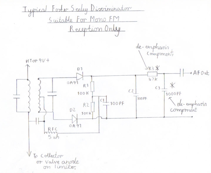
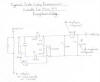
explanation of how to avoid this. Picture 3 is a typical Foster Seeley FM
discriminator found in old transistor portables and valve Hi FI tuners. The
output filter capacitor C3 and the R3 are the De-Emphasis components required to
receive mono reception. These components vary in value and in this particular
discriminator it is set at a time rate of 50 microseconds for UK FM
broadcasting. If you simply leave these components in and connect the stereo
decoder, you will get very disappointing results because these components will
severely distort the 19KHZ pilot tone and stereo signal components leading to
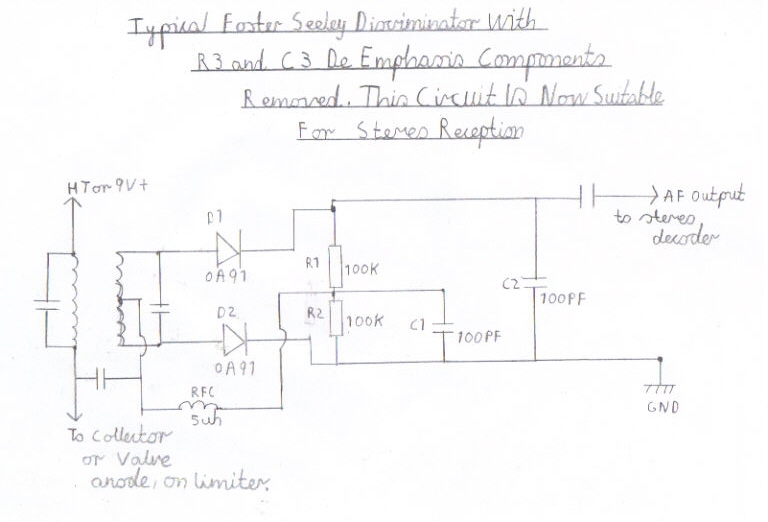
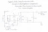
poor separation. Picture 4 is the same Foster Seeley discriminator except the
De-Emphasis components, R3 and C3 are not included. This later circuit should
now be ok for a stereo conversion. Please always bear this in mind before
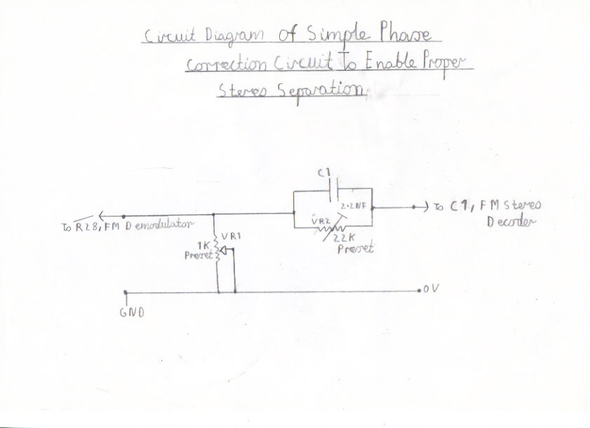
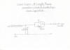
attempting a stereo conversion on a old mono tuner. Picture 1 is a phase
correction circuit designed for tuners that have a low IF response. In the case
of the pulse counting receiver, this is needed for the simple reason. The
Double Conversion Pulse
Counting FM Superhet Receiver With 10.7 MHZ First IF Stage gets its De-Emphasis
from the output RF bypass capacitor C28 on the discriminator. Removing this
component or reducing its value will cause the receiver to become unstable or
not work at all. RV1 on the phase correction circuit, is a simple audio
attenuator to overcome this problem, as it widens the bandwidth to make stereo
reception work properly and is only needed for the pulse counting tuner. RV2 and
C1 is a parallel capacitor network connected in series with the input and the
purpose of these components is to delay the stereo signal components relative to
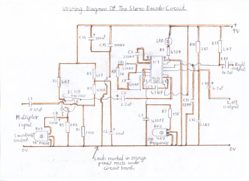
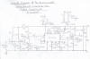
the 19KHZ pilot tone giving a separation of about 30db. Picture 2 is the
suggested stereo decoder circuit which I will explain briefly. The TR1 BC109
transistor forms a input preamp designed for tuners that have a low output
sensitivity and in the case of the pulse counting receiver, this is needed to
overcome the attenuation of the output in the earlier stage to make stereo work
properly. RV1 is the preamp gain control and is adjusted with trail and error,
if signals are found to be overloading the preamp, preventing clear undistorted
stereo reception. RV2 is the VCO voltage controlled oscillator tuning
potentiometer and is adjusted in the anticlockwise direction until the stereo
lamp lights. The stereo lamp can be any low current LED preferably 20 to 40
milliamps. It must be born in mind that you must not draw more then 100
milliamps from the LED output on this particular IC. NB There
is to be an improved version of this circuit around late August which will
involve filtering of the 19KHZ Pilot Tone and an output buffer stage which
should hopefully improve the stability of this circuit when driving various
types of audio amplifier which has been an issue with this present circuit.
|
|
|
|
Stereo phase correction circuit. This circuit must follow the new stereo decoder circuit to enable proper stereo separation in each channel.
|
|
|
|
The suggested stereo decoder circuit complete with input preamplifier to enable stereo reception with the pulse counting FM Receiver.
|
|
|
|
Typical Foster Seeley discriminator found in old mono FM Tuners. The de-emphasis components R3 and C3 must be removed to allow stereo reception.
|
|
|
|
Foster Seeley Disriminator, modified for stereo reception. Notice the de-emphasis components R3 and C3 have not been included.
|
|
|
|
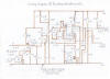
Wiring diagram of the stereo decoder circuit. Leads marked in orange pencil route under the circuit board
|
|
|
|
|
|
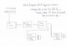
Block diagram of a typical stereo setup, to give you all a good idea of how the circuits are supposed to be joined up.
|
|
|
Wiring and setting up the stereo decoder
1. Please refer to the wiring diagram in picture
5 making sure you follow the polarisation of the electrolytic capacitors,
transistors and ICs very carefully. The 14 pin IC holder in the component list
must be used for mounting the MC1310 decoder IC rather then soldering direct to
the circuit board as this IC is very heat sensitive.
2. Connect the output of the pulse counting FM
tuner demodulator to the input of the phase correction circuit, as shown in the
diagram in picture 6.
3. Connect the output of the phase correction
circuit to the multiplex input on the stereo decoder, as shown in the diagram of
picture 6
4. Connect a stereo amplifier to the left and
right outputs of the decoder. NB If you are
connecting to a valve amplifier, it would be advisable to change the output
coupling capacitors C10 and C11to 470nf 600V rating for safety reasons. Do not
connect to a valve amplifier or FM tuner that incorporates a AC/DC live chassis type power supply
unless you use an earthed isolation transformer or a
serious electric shock hazard may exist. Many table radios of the 1950s and
early sixties fall into this category, including the models made under the
famous brand names of Philips and Bush. Latest update on this subject, Please
read further. The new 3 watt stereo amplifier which can be found at the
following link 3 Valve 3 Watt Stereo
Amplifier already has high voltage polypropylene capacitors incorporated so
you may in that case build this exciting circuit with no modifications.
Also this new amplifier circuit works very well with this decoder circuit and
incorporates a safe isolated chassis which is also properly earthed with no live
transformerless techniques.
5. Hook up a suitable 9 Volt power supply,
preferably independent of the receiver power supply as this unit draws a current
of about 40 milliamps with the stereo LED lit.
6. Turn on the FM tuner and the stereo decoder
7. Tune in a reasonably strong FM broadcast
station that is broadcasting some light music such as Radio 2 or Radio 3 if your
interests are classical music.
8. Advance RV1 on the phase correction circuit
anticlockwise at full resistance.
9. Advance RV1, the preamp sensitivity control on
the decoder, clockwise until you are receiving a undistorted strong signal.
10. If the LED is not lit, advance RV2 the VCO
control anticlockwise until the LED comes on. If this is so proceed to step 11.
11. Although you may think you are now receiving
a crystal clear stereo broadcast, the separation may be very poor until you have
aligned the
phase correction circuit properly. Advance RV1 slowly clockwise
around midway or to a point where you do not attenuate the signal to low. Listen
carefully in both speakers, making a note of the separation affect. If the
separation seems very poor, advance the RV2 phase control anticlockwise at full
resistance until separation improves.
12. If stereo sounds weak with background hiss,
try improving on your antenna system. The directional 5 element beam is the best
antenna to use then these so called rod or unidirectional type for reliable
stereo reception.
13. If you are lucky enough to own one of these
FM tunecast gadgets designed to play MP3s on the car stereo, this will make the
tuning of the phase correction circuit even more easier as you can broadcast
some of your own music that you are familiar with. For instance, If you are a
middle aged 60s music fan of pop groups such as The Fab 4 or the Stones, the
voices are broadcast in one channel and the acoustic instruments in the other
which will make tuning of the separation very precise.
14. Please refer by clicking on the following
link Components List For Stereo
Decoder for the full list of components. I wish you all, Happy FM Stereo
Listening. Also click on the following link
Single Conversion 6
Transistor 10.7 MHZ Pulse Counting Receiver, Designed For Stereo FM Reception
which features a new receiver, designed specially for this decoder circuit and
gives very good performance regarding maximum stereo separation.
Home Page
Links To My FM Receiver And Hi Fi Projects
Suitable For Use With This Stereo Decoder
Transistor Pulse Counting FM Receiver
Double Conversion Pulse Counting FM Superhet Receiver With 10.7
MHZ First IF Stage
6 Valve VHF/FM Pulse Counting FM Tuner Using Safe 25Volt DC HT
Line
Solid State
AM/FM Pulse Counting Receiver
Single Conversion 6 Transistor 10.7 MHZ Pulse Counting Receiver,
Designed For Stereo FM Reception
Valve Version Of
The 10.7 MHZ Double Conversion VHF/FM Pulse Counting Tuner
3
Valve 3 Watt Stereo Amplifier
Simple
Stereo Preamplifier Circuits For The 3 Valve Stereo Amplifier
Component
Suppliers
Site Map
Of All My Webpages And Favourite Valve Radio Related Links