Severn Valve HF Superhet Receiver Designed For Advanced Constructors
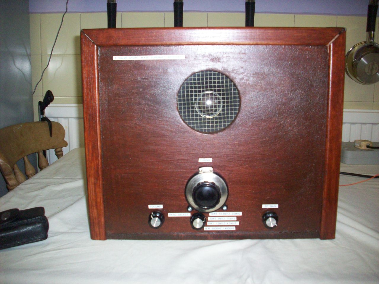
Following the great success of my transistor FM superhet receiver I am pleased to tell you all, It is nice to be back with valves again and I am now featuring a 7 valve short wave superhet receiver designed for advanced constructors only. The reason I say advanced is because it is not suitable for complete newcomers to construct this type of radio receiver for the following reasons. A superhet receiver even if constructed correctly will fail to work first time, until certain stages such as the RF, Mixer, Oscillator and intermittent frequency circuits are properly aligned which requires patients and a idea of how a superhet receiver works. If you have built my Simple 2 Valve Regenerative Receiver I would suggest you also visit the following link 3 Valve Regenerative Superhet Receiver which tells you how the superhet receiver works and there is a simple converter circuit which will form the front end of this design. Also please take note of this following warning regarding certain component availability. IF transformers for valve receivers have not been manufactured for the past 40 years or so and the only way to obtain them is to part with an old valved receiver. However. I have got some good a news on how to overcome this problem. Transistor IF transformers can not be used as single units because they have a low impedance winding, suitable only for coupling to bipolar transistors. To overcome this problem you can use two units by wiring the two coupling windings back to back. If anyone reading this page is lucky enough to have a copy of the December 1996 issue of short wave magazine, Ray Loveland featured an article on page 40 on how to do this. I built my valve superhet receiver, Copying his idea but for extra safety I used high voltage disc ceramic isolating capacitors between the two windings, Because as these winding are very fine I think there could be a possible risk of voltage breakdown. I would also not recommend using a HT supply of more then about 150 volts for this reason. This receiver incidentally does not have to be a complete 7 valve superhet receiver and if your interests are only broadcast band listening, You can omit the BFO Beat frequency oscillator section as it is only used to resolve CW Morse and single sideband reception. The RF amplifier can also be omitted as it is only an optional item used to improve image response and improve selectivity of the receiver. The receiver can also work with a 1 stage IF amplifier, Reducing it to 4 valves, Although the gain and selectivity will be slightly lower with a reduction in performance on the lower HF Bands regarding sensitivity. I am pleased to tell you all that there is now a video clip of this design working in its new chipboard case and is available to view by clicking on the following link YouTube - My Home Built 7 Valve HF Shortwave Superhet Receiver.MP4 . Latest enouncement regarding changes to this page. I will be featuring a new version of this receiver as it has come to my attention that the EBC81 Detector and audio preamp valve is very hard to obtain. An EB91/6AL5 voltage doubler arrangement and ECL82 Audio Amplifier will replace the current EL84 arrangement. Please bear in mind that change will take place around mid summer due to other demands on my time as part of the new refurbishment of this website.
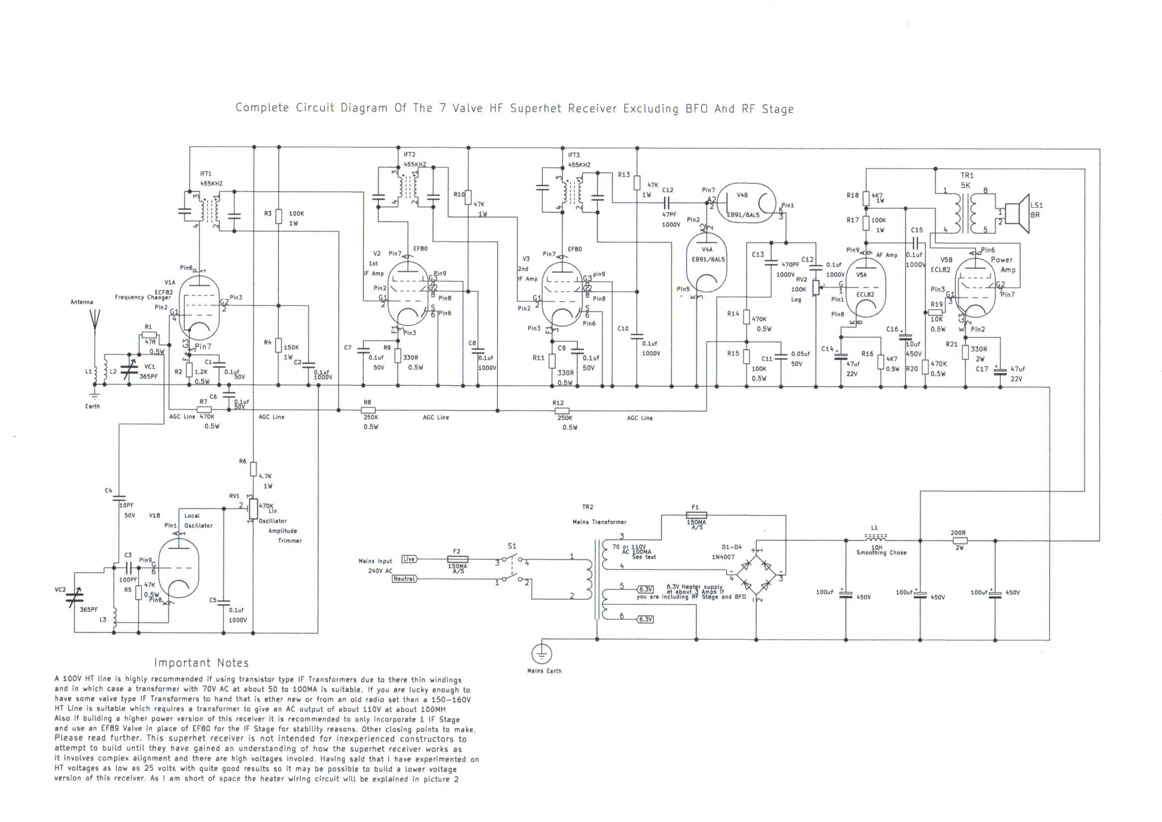
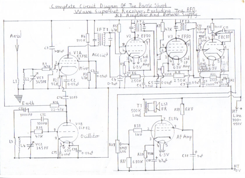
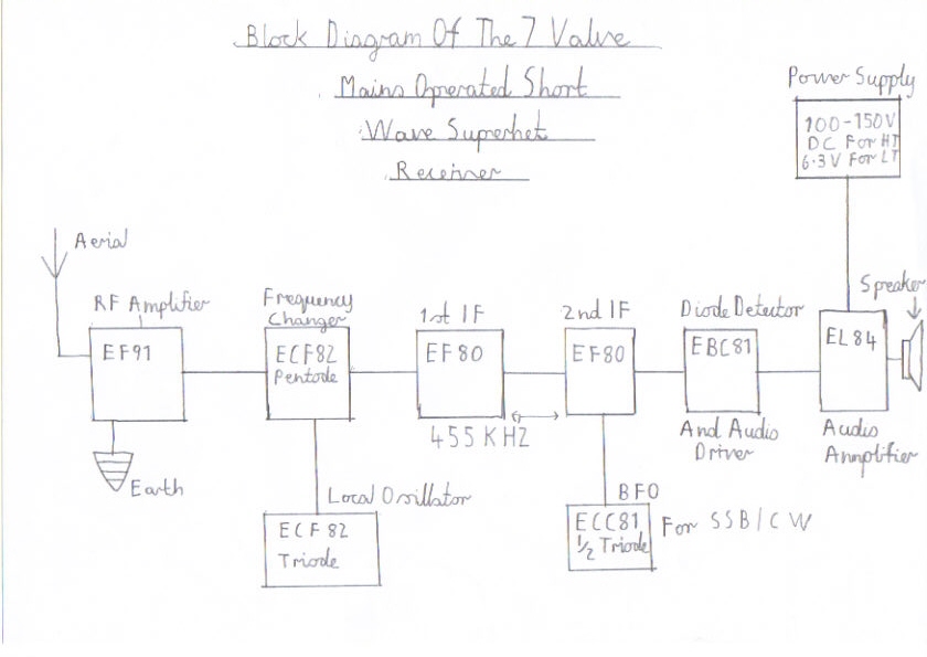
Block diagram of my basic short wave superhet receiver
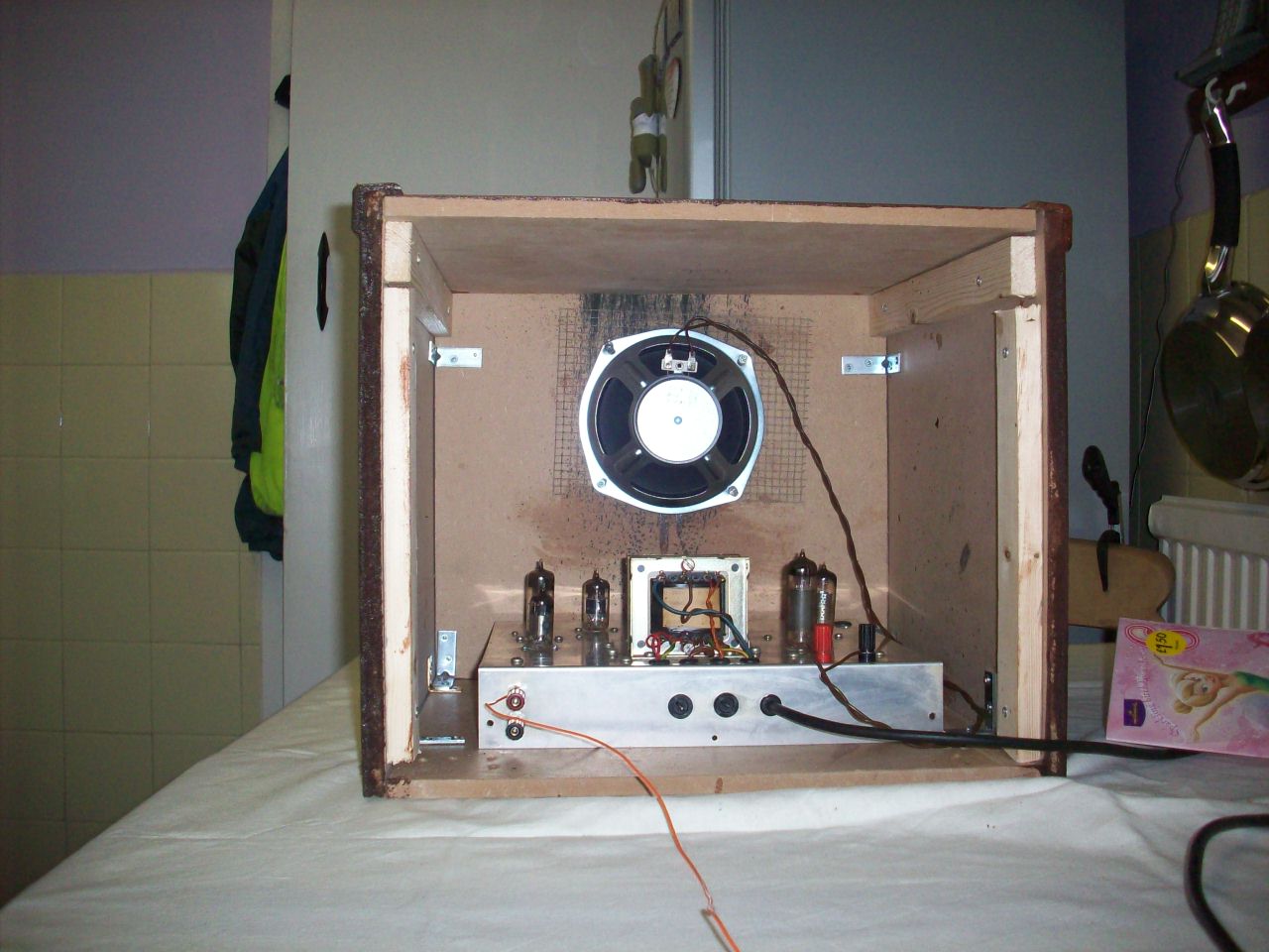
Construction Details Of This Receiver
Please refer to the pictures below regarding construction details.
|
|
|
|
|
|
|
|
|
|
|
||||
Please left click on selected picture to enlarge image
Step 1of the building sequence
Please make sure you have all the components available to hand before even attempting to build this design as some of the items such as the IF Transformers and RF coils may not be easily available and you may have to seek out an suitable alternative to the ones I have listed. Please refer to the following link for the full component list for the receiver Components List For The Severn Valve HF Superhet Receiver
Step 2
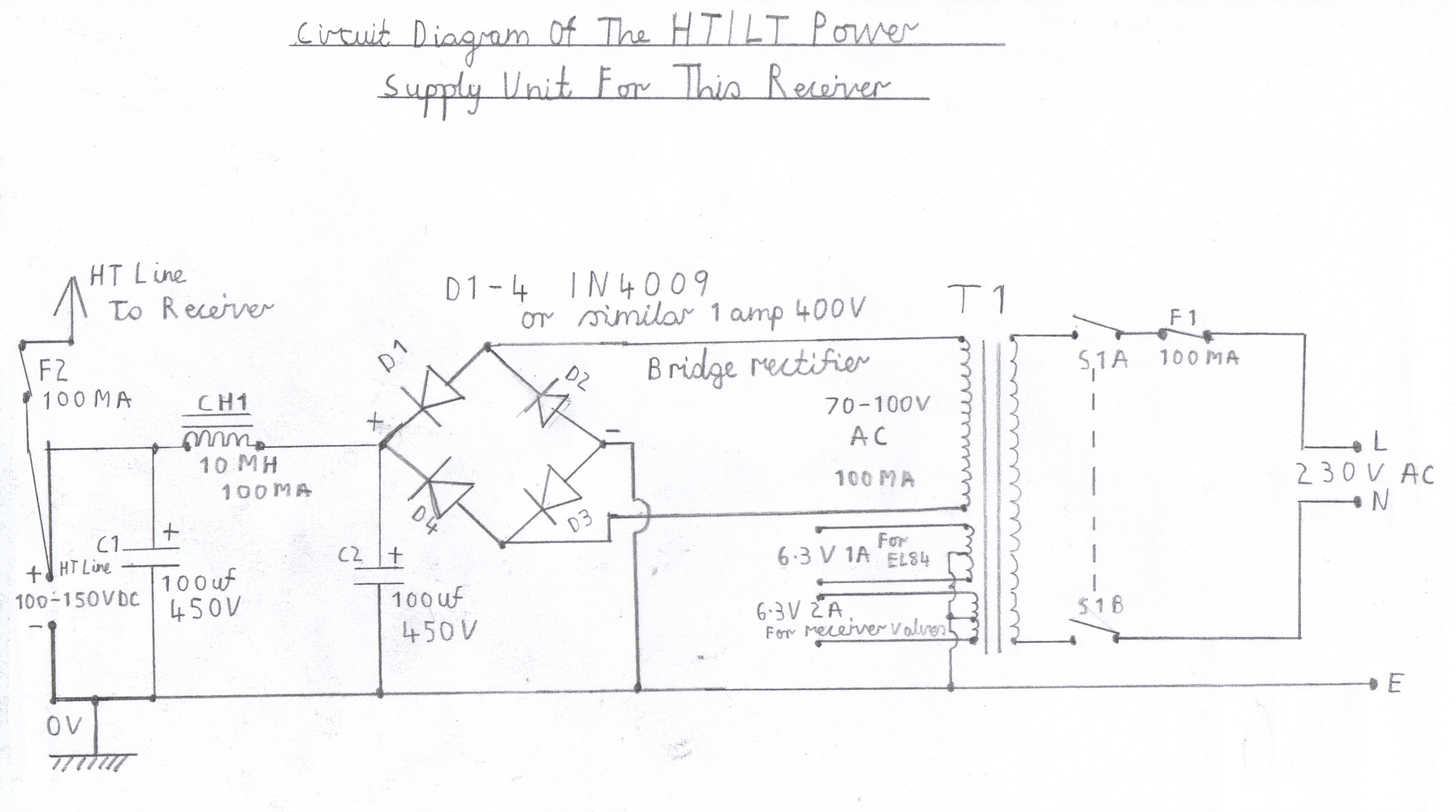
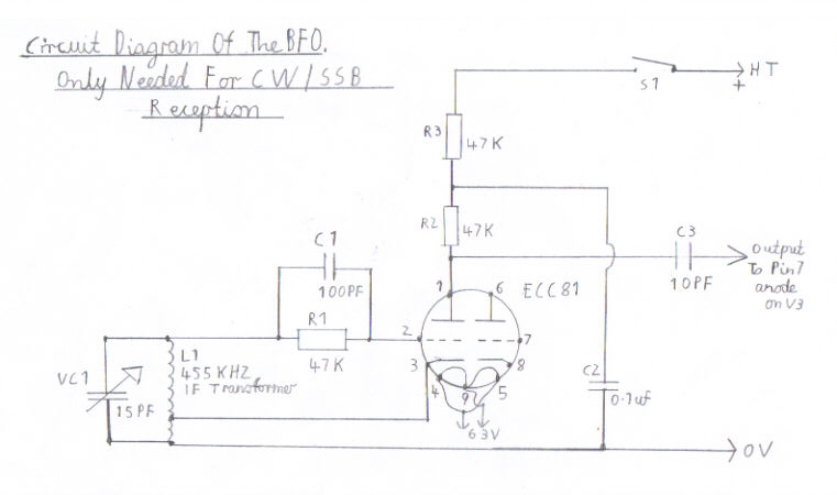
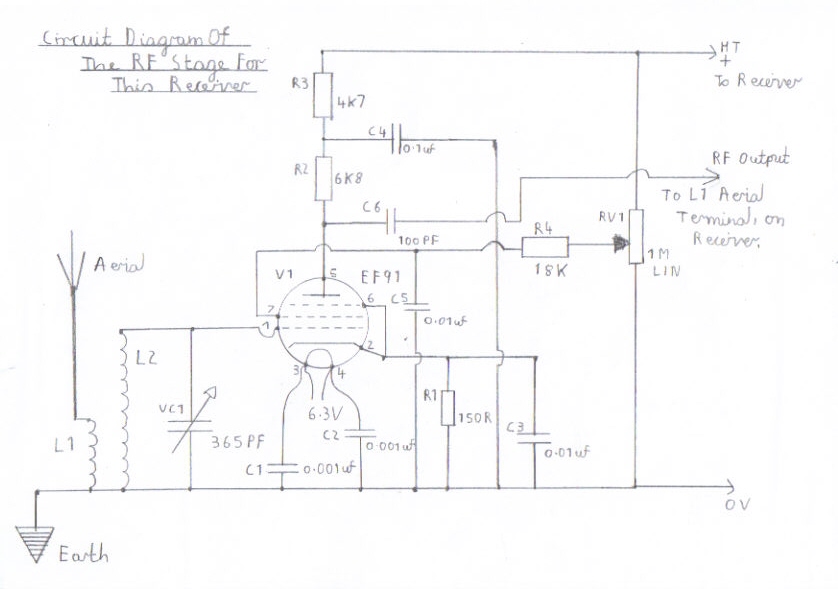
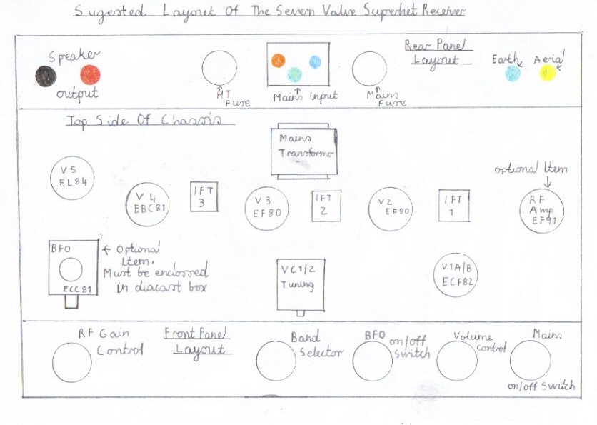
If you are a experienced constructor with transistor circuits, But have never had experience with valves I would suggest you visit the following link Important Electrical Safety Issues Related To Valve Equipment as there is dangerous high voltage involved with these type of circuits. Pictures in the order of 1 to 5 feature all the circuit diagrams to form a complete working receiver with all features such as a BFO and RF Stage. Please refer to pictures 1 and 2 if your interest is just a basic working receiver. You will need to refer to picture 3 if you wish to use the receiver for amateur band listening, As you need a beat frequency oscillator circuit for the reception of CW Morse or SSB single sideband transmissions. Picture 5 is another circuit for an optional RF amplifier and it improves the receiver against second channel interference and also improves gain on the lower frequency bands such as the 80 and 160 metre amateur bands and also the 75 metre tropical band. Picture 5 shows the best recommended chassis layout of this receiver and if built properly it is capable of excellent performance. Experienced constructors may if they wish, Providing they have all the components available to hand, Start building this design. Please refer to step 3 for information regarding the underside chassis and the wiring sequence.
Step 3 Component and chassis preparation
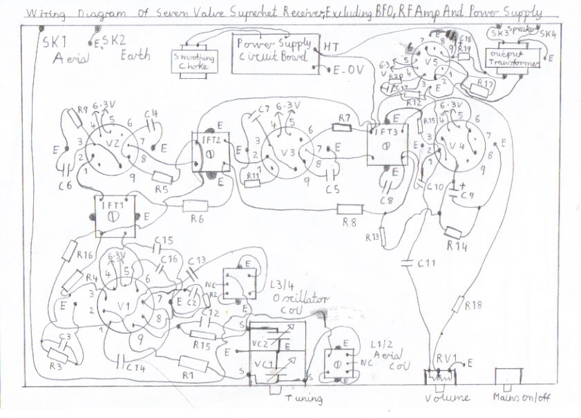
It is best to first mount all the required components on to the chassis first including the power supply circuit boards, Mains and output transformers. Picture 7 is the suggested wiring diagram of the basic receiver and for simplicity to avoid cramming up the diagram I have not included the power supply circuit, RF Amplifier or the BFO. Please note that Points marked E on the wiring diagram are chassis earth points and solder tags are used. To ensure there is proper continuity please make sure that the chassis is free from grease, By cleaning with the proper degreasing solvent and gently scraping the solder tags clean with a small file. Picture 8 is the recommended circuit board layout for the IF transformers when using The transistor Toko YRCS11098AC type and the capacitors C1 B and C2 B must not be omitted or there may be risk of voltage breakdown resulting in damage to the IF valves V2, V3, and V4 resulting in the valves running hot, Due to higher then normal grid bias voltage. Capacitors marked with a Plus + sign must be connected in the correct polarity as shown on the diagram or these components will be permanently damaged resulting in explosion. The same also applies to the rectifier diodes in the power supply circuit. To ensure stability do make sure the wiring is as short and direct as possible particularly in the RF and Frequency changer circuits. A circuit for band switching has not been provided although it is possible provided you make sure that the higher frequency band RF coils use the shortest route of wiring as mentioned previously to ensure maximum performance.
Step 4 Wiring the receiver
If you have followed through step 3 correctly, You may now proceed with all the major wiring. It is best to start by wiring the valve heaters first as these may be a fiddly job if left till later on and make sure the wiring is not routed to close to the IF connections or other components or this may encourage hum modulation spoiling the otherwise good performance of this set. C15 and C16 on the V1A / V1B ECF 82 frequency changer valve are there for the same reason to prevent hum modulation on the higher frequency short wave bands and must not be omitted. As well as being screen dropper and voltage stabilizing resistors for the V1A frequency changer R4 and R5 also take care of discharging the HT smoothing capacitors in the power supply provided the HT fuse has not blown. If you are confidant you have followed all the above tasks and instructions correctly you may now go on to testing and alignment of this receiver.
Step 5 Testing and aligning
First of all before throwing the big switch in great excitement, Please double check that all connections regarding the mains wiring and components such as the HT smoothing capacitors and rectifier diodes are connected in the correct polarity. Please visit Important Electrical Safety Issues Related To Valve Equipment for more information on safety. Start by inserting the mains, HT Fuses and the valves in the correct holders. You next need to connect a speaker and about 5 feet of aerial lead as a start. Although you may have wired everything correctly a superhet will not always work straight away until certain stages of alignment have been carried out which requires patients and is best done during mid day to early evening on the higher frequency bands and mid evening to the early hours of the morning on the low frequency bands such as the 80 metre amateur and 75 metre tropical bands. This is now the big true moment. You need to turn the chassis upside down and it must be supported temporarily with wooden blocks of some sort. When first testing stand at least 3 metres away till you are sure nothing unexpected is going to happen which is likely to be a smoothing capacitor exploding due to incorrect polarity. Allow 2 minuits for the valves to reach working temperature and turn the volume control fully clockwise. You should now hear a hissing sound in the speaker and by touching the middle wiper on the volume control you should also hear a high pitched hum which means the audio stages are working. Try rocking the tuning capacitors VC1 / 2 and if you are lucky you may be able to tune in at least a couple of strong stations. If this is so try adjusting IFT 1 for maximum signal strength. Next do the same with IFT 2 / 3 and the signal strength should further improve. Repeat this step several times as each adjustment affects the other until no further improvement can be obtained. If all is well you may now proceed with the RF Tuning alignment. Depending on which band coil you are using an RF signal generator is the best option if available. Try tuning to some weak stations on the middle part of the band. Adjust the L1 / L2 RF coil for maximum signal strength. Repeat these steps several times by tuning to the high and low frequency part of the tuning range until no further improvement is possible. You now need to adjust the tuning range which is a little more tricky and is done with trail and error when no signal generator is available, By the aid of a portable shortwave receiver. I will give you a brief example. The range 2 RF and Oscillator coils cover 4.5 MHZ to 15 MHZ when using the Jackson 350PF variable capacitors. With the aid of a signal generator connect the black crocodile clip of the signal generator to the chassis of the receiver, Preferably the Earth terminal. Next connect the red RF probe through a 100PF high voltage disc ceramic capacitor to the aerial terminal. Tune the receiver to the middle part of the band and using tone modulation, Tune the signal generator until you hear a high pitched tone. Slowly rock the tuning capacitor to the low frequency part of the band and adjust the signal generator in the same direction at the same time. Adjust the L1 / L2 RF coil for maximum signal strength. When you are near the lower extreme part of the tuning range make a note of the frequency. If it is about 6 MHZ for example slightly adjust the L3 / 4 oscillator coil. Retune the signal generator and if the frequency is lower, Say about 5.5 MHZ retune the L1 / 2 RF Coil for maximum signal strength. Repeat these steps about two or three times on the low and high frequency end of the tuning range to correct the required band coverage. Please note that if you align the IF Intermediate Frequency circuits using the signal generator, Start from V3 anode and work your way up to V1A anode, Maintaining the adjustment of each IF transformer as you work upwards for maximum signal strength. To prevent high voltage damage to the signal generator always make sure high voltage disc ceramic capacitors are used, Preferably no lower then 1000V and are connected in series with the red RF probe. When adjusting the RF and intermediate frequency circuits do not use screwdrivers or other metal objects as there is a high risk of jamming or cracking the delicate cores of these coils. When ordering the coils make sure you also get the recommended plastic trim tools preferably from the manufactures or TV engineer. If you have or are thinking of adding the BFO or RF Amplifier stages please refer to step 6.
Step 6 RF Amplifier and BFO Circuit
The RF amplifier and BFO circuits are optional items and are not included in the receiver wiring diagram. Because this page is aimed mainly for experienced constructors I presume that you should already have the necessary experience if you have built a fully working receiver. The RF amplifier is aligned the same way as the RF Mixer and the RF coil is identical but it must be also in the same tuning range. Its purpose is to improve selectivity particularly on the high HF bands 14 to 30 MHZ and does have the advantage of increased gain on the low frequency bands. The BFO is required for the reception of SSB Single Sideband and CW Continues Wave, Morse reception. This is very easy to build and is best enclosed in a diacast metal box to prevent radiation. It is simply a oscillator working at 455KHZ the same intermittent frequency of the receiver and is injected into the last IF stage. Adjusting the pitch of the BFO is with trail and error and is best done in the early evening with the receiver tuned to the 80 metre band for aligning for lower sideband. For upper sideband alignment, 20 metres is the best band from say mid morning to virtually all day during the summer months. I wish you all success in building this design and hope you can obtain the components OK without to much difficulty
Link To My Other HF Shortwave And Medium Wave Related Receiver Projects
Simple 2 Valve Regenerative Receiver
3 Valve Regenerative Superhet Receiver
Solid State AM/FM Pulse Counting Receiver
Simple (ATU) Antenna Tuning Unit For All HF Receiver Projects
Site Map Of All My Webpages And Favourite Valve Radio Related Links