Simple Stereo Preamplifier Circuits For The 3 Valve Stereo Amplifier
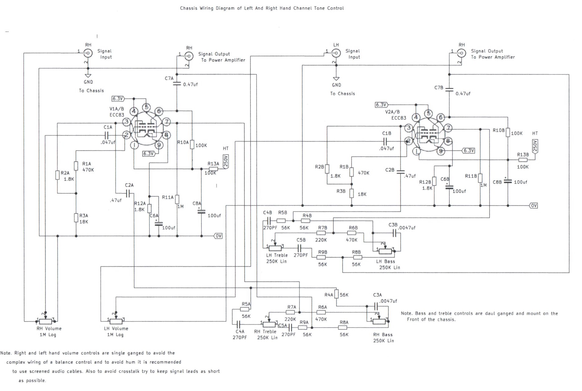
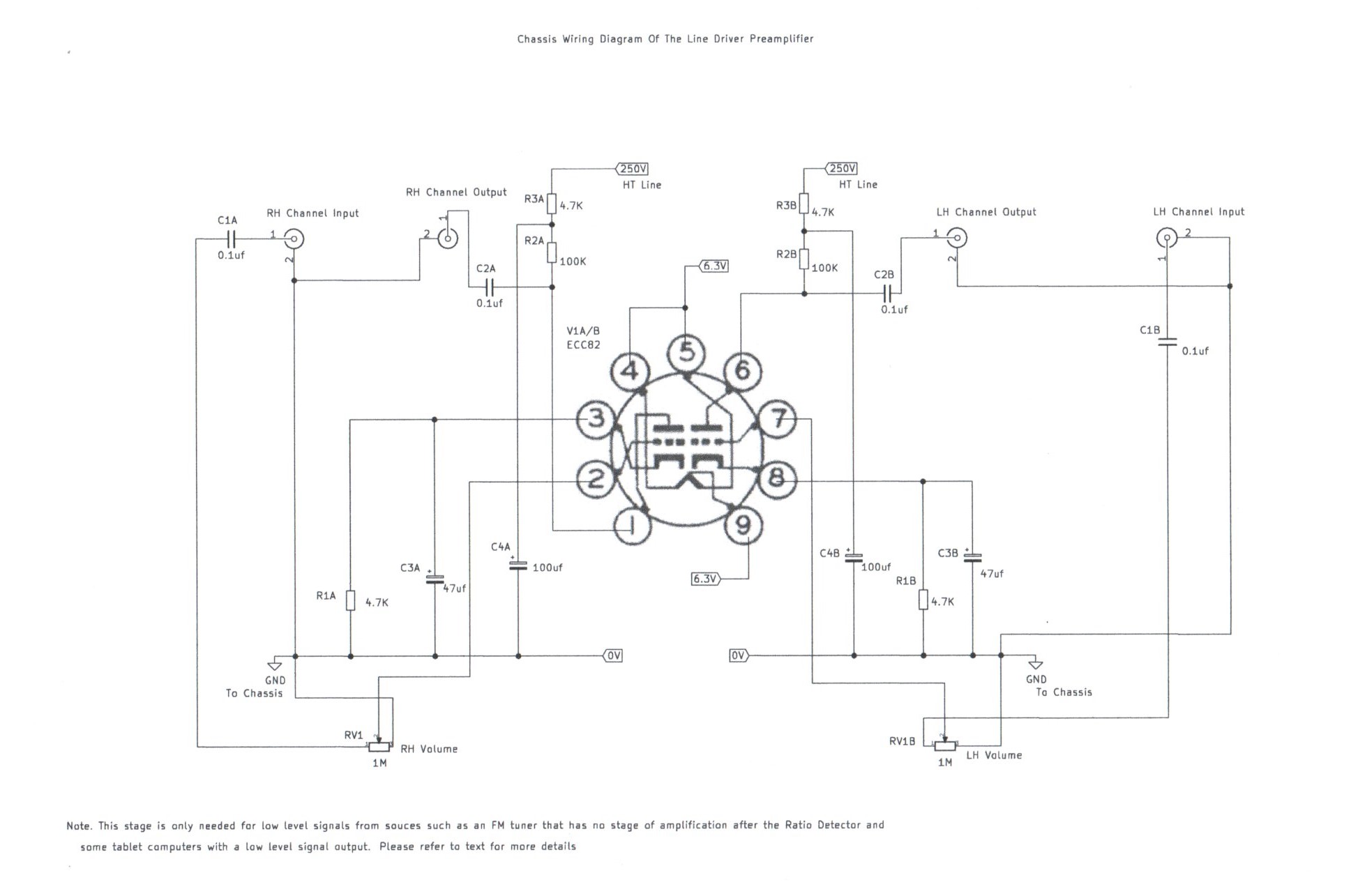
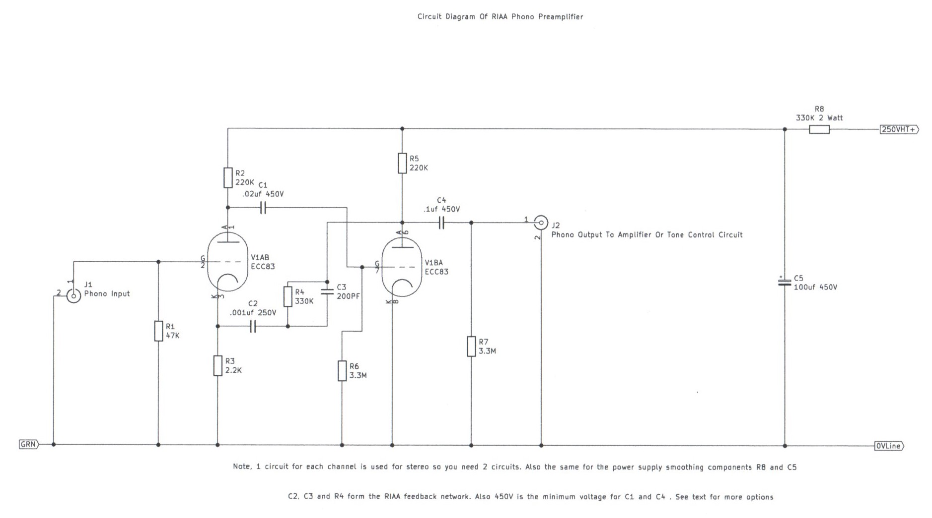
At last and after a long 7 year wait, I am pleased to present you with a decent Phono and tone control preamplifier circuit to compliment the 3 valve stereo amplifier. This project is split into 3 individual circuits which I will briefly describe. A 2 Valve Phono preamplifier designed to be used with a magnetic cartridge for the reproduction of records and a 2 Valve tone control circuit with individual bass and treble controls. Also a line level preamplifier which may be needed for the amplification of of low level signals to drive the tone control circuit properly. To cut the story short on finding suitable circuits I was having a look at the Mullard 2 Valve Preamplifier, A popular Hi Fi project during the 1950s and early 60s as a possibility but thought it had unnecessary complicated input selector switching for the phono equalisation network and was looking for something simpler. Also during the 1990s I did build a project which was featured in Maplin Magazine which was where I got part of this idea from and can be downloaded at the following link https://worldradiohistory.com/UK/Mapelin/Maplin-Electronics-1995-01.pdf . It was a stereo preamplifier project to compliment there millennium valve power amplifier project and although the project worked as it said and well presented I will briefly tell you the good and the bad. Like there millennium project you could spread the cost as it was split into 3 monthly articles such as the power supply, Phono Preamplifier and the tone control circuit as the final project. The performance was not bad for its price but the tone control and line preamplifier circuits were unnecessarily biased near to there maximum limits allowing the valves and transformer to run rather warm and there was a slight mechanical buzz which was probably the main reason in which the project did not gain further popularity a few years further on. This design that I feature is split into 3 modules which I will describe the power supply unit first. Referring to picture 3 the power supply uses the same transformer and rectifier configuration as used in my 3 valve stereo amplifier and will power all the 3 modules without any stress as each module only consumes a few milliamps. A separate resistance smoothing capacitor filter is used in each module to ensure stable regulation. Because the HT voltage is the same as the 3 valve stereo amplifier it is also possible if for example you only want to build the phono preamplifier or the tone control on its own, Use the HT and Heater Supply from the main power amplifier. Because the maximum heater current is 3 amps I would not advice trying to power all modules off the main amplifier supply as you would be pushing the mains transformer to its extreme limit. Tone controls weather you like them or not was a regular feature on Hi Fi Stereo systems up to the mid 1980s and I certainly prefer using them as it shapes the music mood with the sound and I am one who does not like to much treble to which it sounds excessively tinny or to much heavy bass. Picture 4 is a suitable circuit consisting of an ECC83 double triode per channel which I will briefly describe. The first section V1A is a simple cathode follower circuit and although it does not provide any voltage amplification or gain its purpose is to isolate input sauces from heavy loading the tone control network. A low impedance Baxandall tone control follows V1B which uses feedback to provide constant gain at all treble and bass settings resulting in good stable performance. The tone control will work with most signal sources such as CD Players and most modern gadgets such as the like of Tablet computers or MP3 Players which I will describe the purpose of the line level preamplifier which is picture 6. This circuit is only really needed for low signal sources such as the sort of equipment that does not incorporate built in preamp circuitry such as old radio tuners that relie only on the signal from the diode or ratio detector circuit. Also using this circuit for all line level sources will result in improved performance except you may need to add some output attenuation to avoid signal overload. I will now describe the purpose of the Phono preamplifier. For good Hi Fi reproduction of records a record deck with a magnetic or moving coil pickup is required which needs additional amplification for the low impedance signal. Courtney to popular belief during the early launch of the CD Compact Disc Player during the early 80s, Many of the new generation who had not heard what early 1960s vintage Hi Fi sounded like thought vinyl was dead and sounded very mediocre only because of the following reason which I will briefly describe. Many people relied on the simple BSR record decks designed for low cost that had a ceramic or crystal pickup head which only needed simple amplification and this configuration ran from the 1950s Dansette record player era to the so called music centre Hi Fi systems of the late 1970s. Picture 8 is a suitable Phono preamplifier circuit which I will briefly describe. Like the tone control circuit an ECC83 double triode is used for each channel with each stage connected in cascade. R1 sets the bias conditions for V1A at 47K which should suit most magnetic cartridges and may be altered for different input signal loads. R4 C2 and C3 form the RIAA equalisation network connected in feedback mode from the anode of V1B to the cathode of V1A. This now describes the operation of all modules that form a simple to complete Hi Fi System and you must refer to picture 11 which gives you a full example of how these circuits should be used. Like the 3 Valve 3 Watt Stereo Amplifier these circuits require the use of high voltages so great care must be taken in the construction. On a closing note this is the first page to not have hand drawn circuit diagrams and there is no longer going to be any component lists for future projects as there full values will be on the new circuit diagrams. It is assumed that you must fully understand circuit diagrams and safety regarding high voltages before even thinking of constructing any of these projects. Please refer to the text below for construction Guidelines.
|
|
|
|
|
|
|
|
|
|
|
||||
Please left click on selected picture to enlarge image
Construction Guidelines For All Configurations Of These Circuits
1. I have provided a circuit diagram for each module you wish to construct and this includes the value of every component and the voltage rating of capacitors in which where highlighted is the minimum which can be used. All resistor values are 0.5 Watt except for the power supply smoothing resistors in which case are called for in the circuit diagrams.
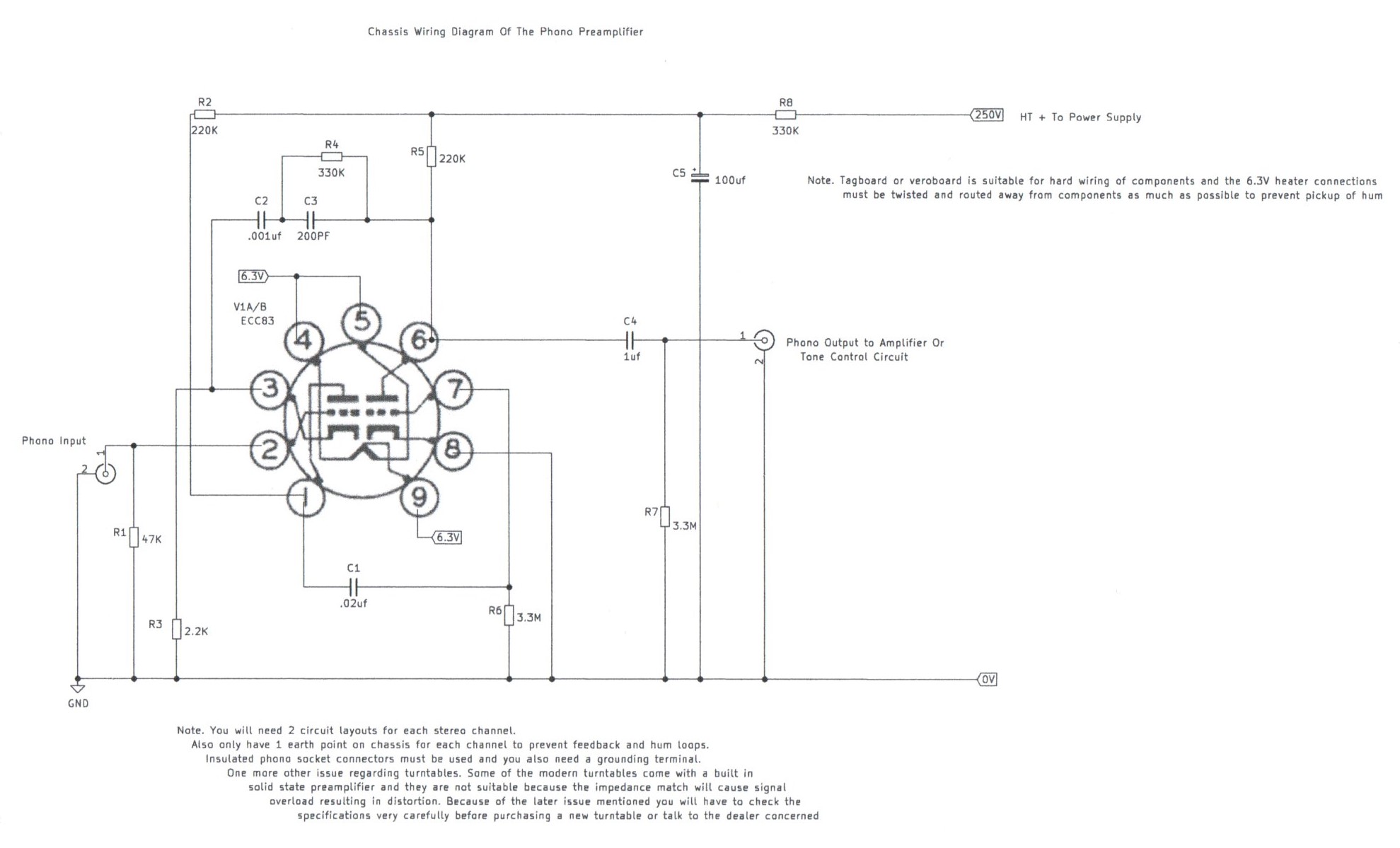
2. The wiring diagram is the suggested chassis layout and until I obtain some suitable symbols it only shows the valve base connections mounted under the chassis.
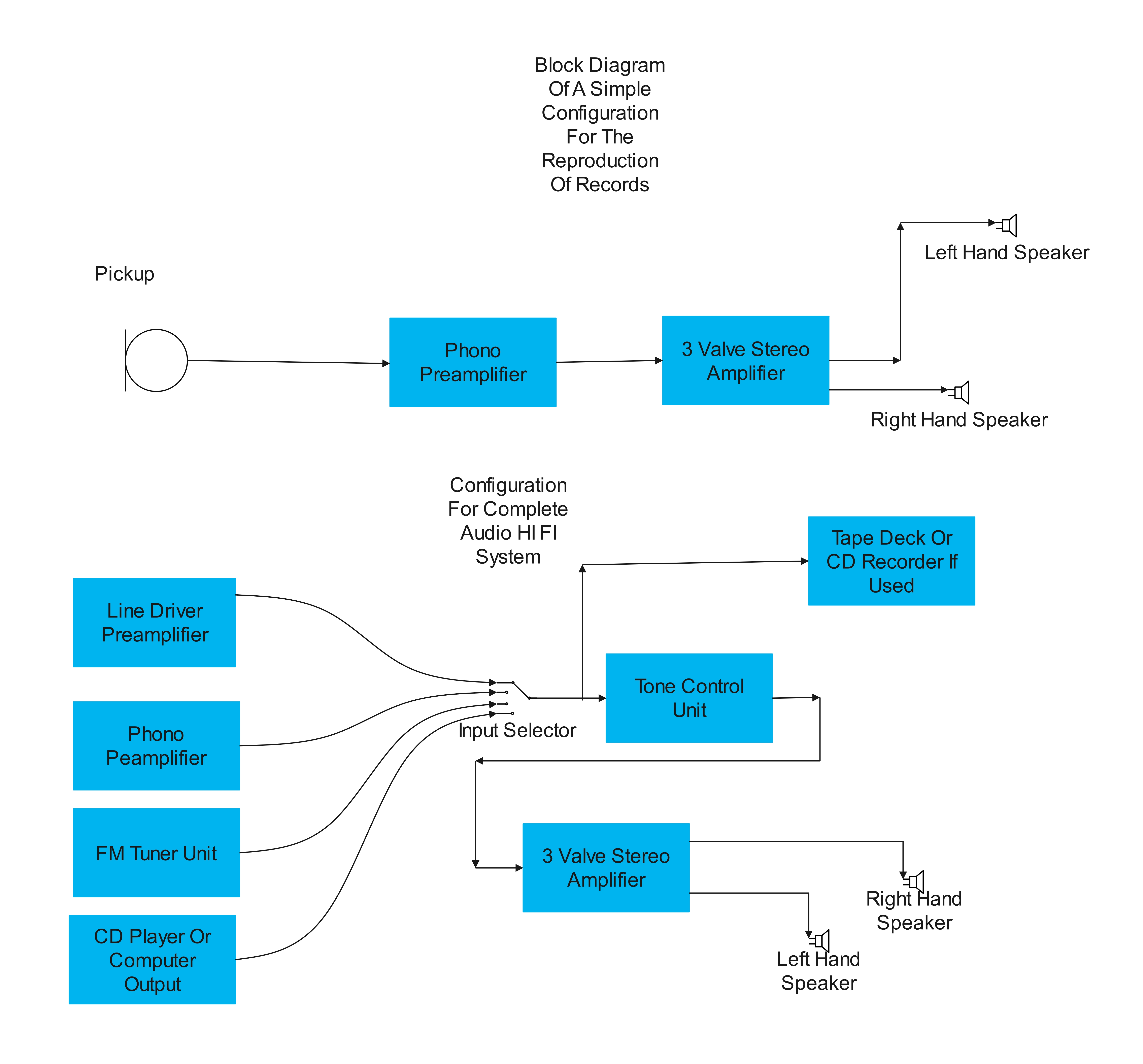
3. There is not really any setting up procedure of any of these modules and if in any doubt picture 11 is the block diagram which shows you how to connect these modules up.
4. All these circuits involve the use of very high voltages and although they are very simple you must have proper respect for mains electricity. All modules including the power supply unit must be enclosed in a soundly earthed metal case or chassis with no exposed live connections accessible.
5. Unless you are building everything into an instrument metal case, Ventilation is not a big problem like the 3 valve stereo amplifier as the HT current draw is very low.
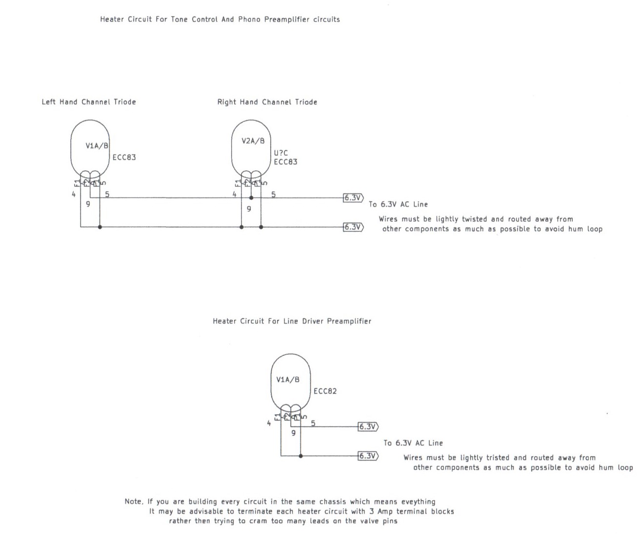
6. As a final precaution try to keep all wiring short and direct such as not too crammed up. Also make sure the valve heater wiring is routed further away from sensitive input circuits such as the Phono preamplifier. You must make sure all polarised components such as the rectifier diodes, Electrolytic capacitors are connected in the correct order or damage may result. Also a brief description regarding the resistor R1 in the power supply circuit, Please read further. This resistor is to stop the smoothing capacitors from holding a lethal charge when everything is switched off. Please bear in mind that it may take about half an hour for these capacitors to fully discharge and also if you disconnect any of the modules it is possible for these capacitors to recover a charge from the module concerned so be very careful.
7. Before testing everything double check your work for any mistakes and as you are connecting everything up for the first time it is advisable to place the chassis upside down so it is not pointing directly at you in case something unexpected happens. The most common mistake is connecting the smoothing capacitors with incorrect polarity which would explode and as an added precaution use a switched socket outlet which is located at least 2 metres away keeping your hand on the switch.
8. Any fault like mentioned above will blow the HT and mains fuses immediately protecting the mains transformer from serious burnout. Do not use any higher value then stated in the text and do not use foreign objects such as cigarette paper or tin foil as this could result in serious damage or a fire. If the fuses are repeatingly blowing or after a period of heavy use there is a fault and must be investigated before proceeding any further.
9. A brief word about purchasing a record deck to use with the phono preamplifier. Some record decks nowadays already have a built in solid state preamplifier and you must look at the specifications very carefully or talk to the dealer concerned as these sort of turntables are not suitable and if you attempt to connect these to the phono preamplifier serious overloading will occur causing distortion.
10. On a closing note I wish you happy building of all these Hi Fi modules which if correctly used will form a very high quality vintage Hi Fi system for the home user. Also I may make improvements to this article with additional circuits as time permits.
Links To My Other Hi Fi Webpages Related To This Article
3 Valve 3 Watt Stereo Amplifier
6 Valve VHF/FM Pulse Counting FM Tuner Using Safe 25Volt DC HT Line
Site Map Of All My Webpages And Favourite Valve Radio Related Links