Transistor Pulse Counting FM Receiver
This part of my site features construction details of a transistor VHF radio I managed to build using circuits as the building blocks, Compiled from some of my old radio magazines and books. Although this site is titled as a valve radio site I have decided to include transistor radio projects as well and having successfully built a valve version of this type of FM Receiver, I have since been itching to have a go at a transistor version for use in the garden and when I go on holiday. The valve version I constructed which is featured on some of the home page pictures referring to my valve portable Hi Fi System is not strictly my own design, But can be found by clicking on the following link Cool386's Australian Site of Vintage Technology an excellent website run by John Hunter who also has some great FM Radio circuits and also an update on his valve version of the pulse counting receiver by clicking on this link Pulse Counting FM Receiver (cool386.com) . Part of the idea of this design also came from a similar transistor version featured in the August 1967 issue of Practical Wireless. The PW version was slightly behind time. It was featured as a switched version with the Channel positions marked as Light Third and Home, Only just 2 months before the BBC Launched there new network of stations, Starting with Radio 1 available on Medium wave only and Radio's 2 3 and 4 to replace the exciting three networks. The PW version although very good at the time had several disadvantages. It used the old Germanium OC171 transistors that had a reputation for being unreliable, Compared to the later Field Effect Transistors such as the 2N3819 series that were apparently just available at that time and could have easily been substituted for the RF / Mixer circuits, Despite a few circuit modifications. The idea of switched tuning is very convenient but that also has a couple of disadvantages regarding RF performance. In the days of Light Third and Home this was not a problem as there were no Local Radio Stations around at that time, So there was not the need to have to keep tuning like you sometimes do to get a clear station without interference from other channels. Also the idea of bandswitching is not my scene when it comes to VHF work because as you are dealing with a high frequency of 100 MHZ, Leadless connections to the coils and tuning capacitors are strictly the order of the day, As the risk of poor performance and instability is very high compared to the Short Wave Bands.
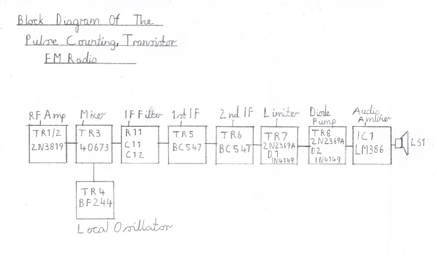
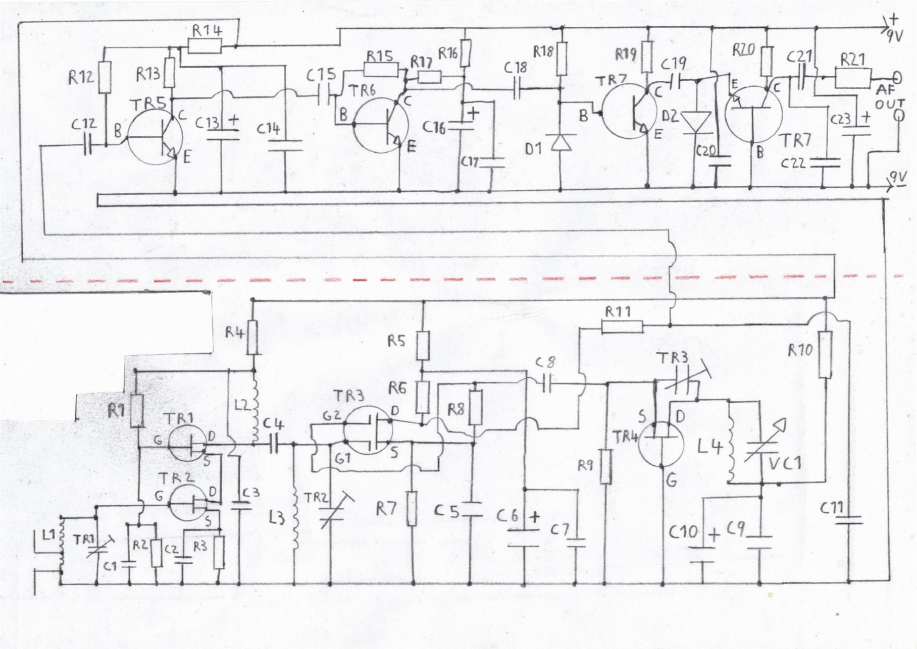
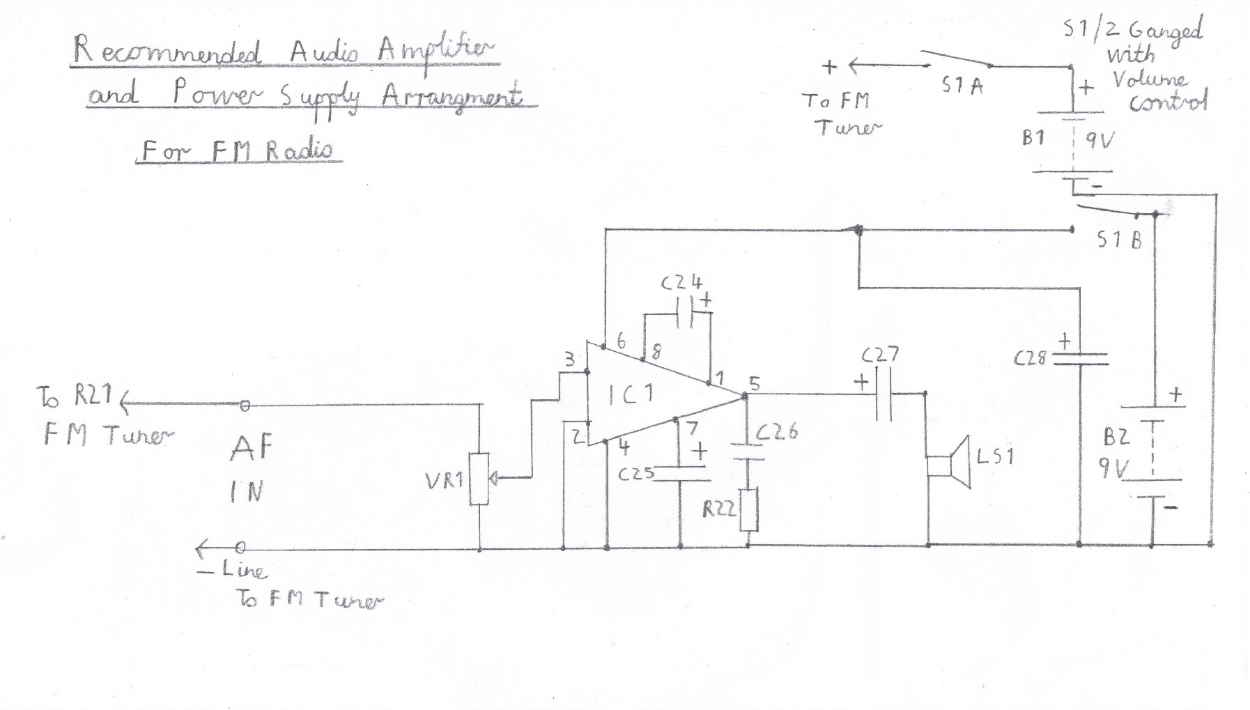
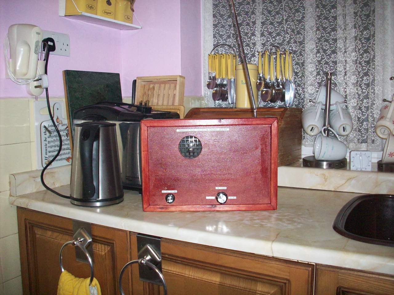
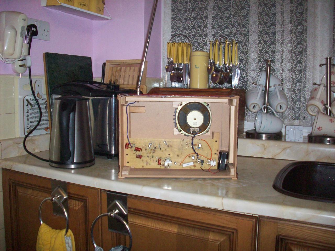
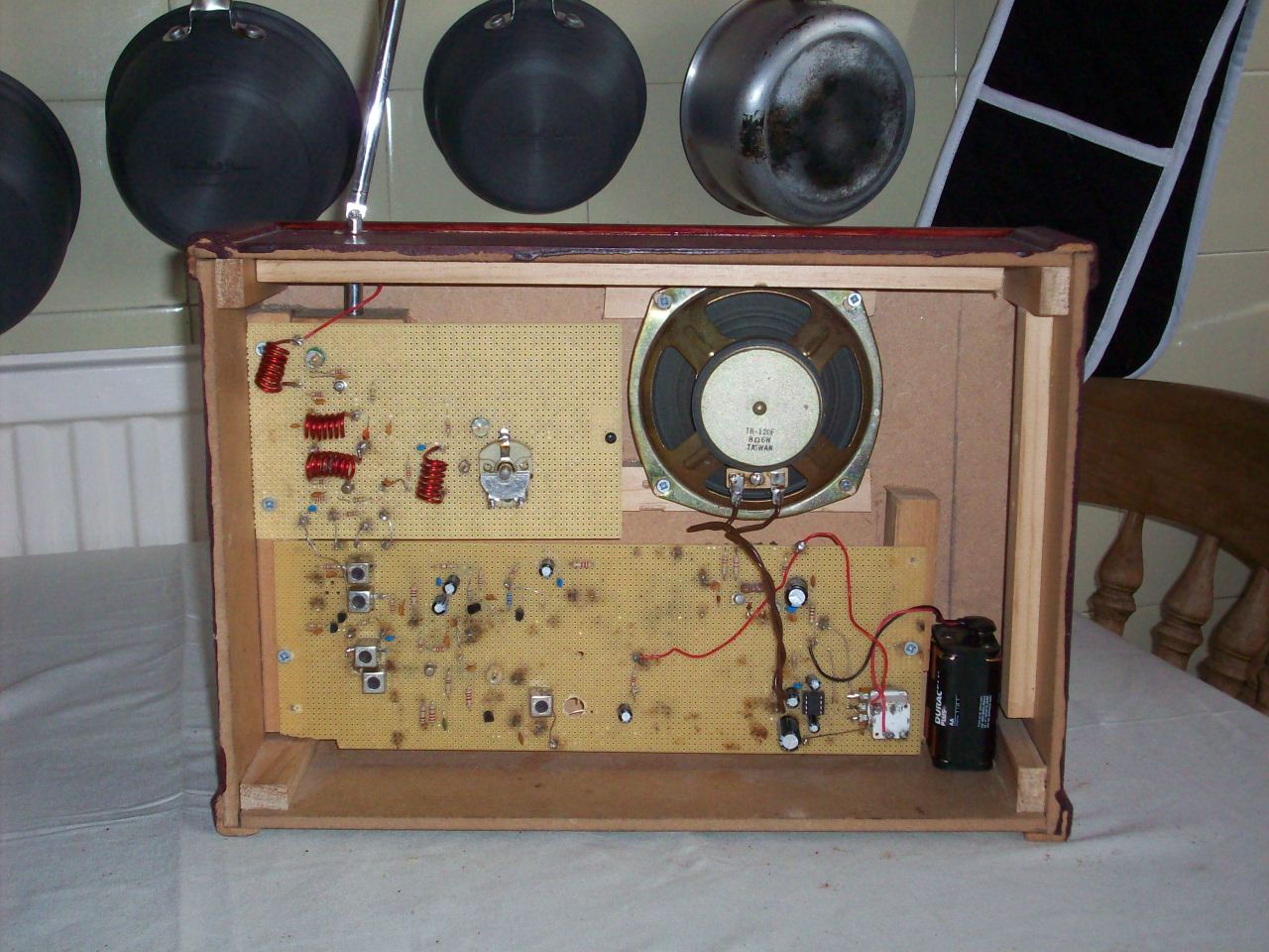
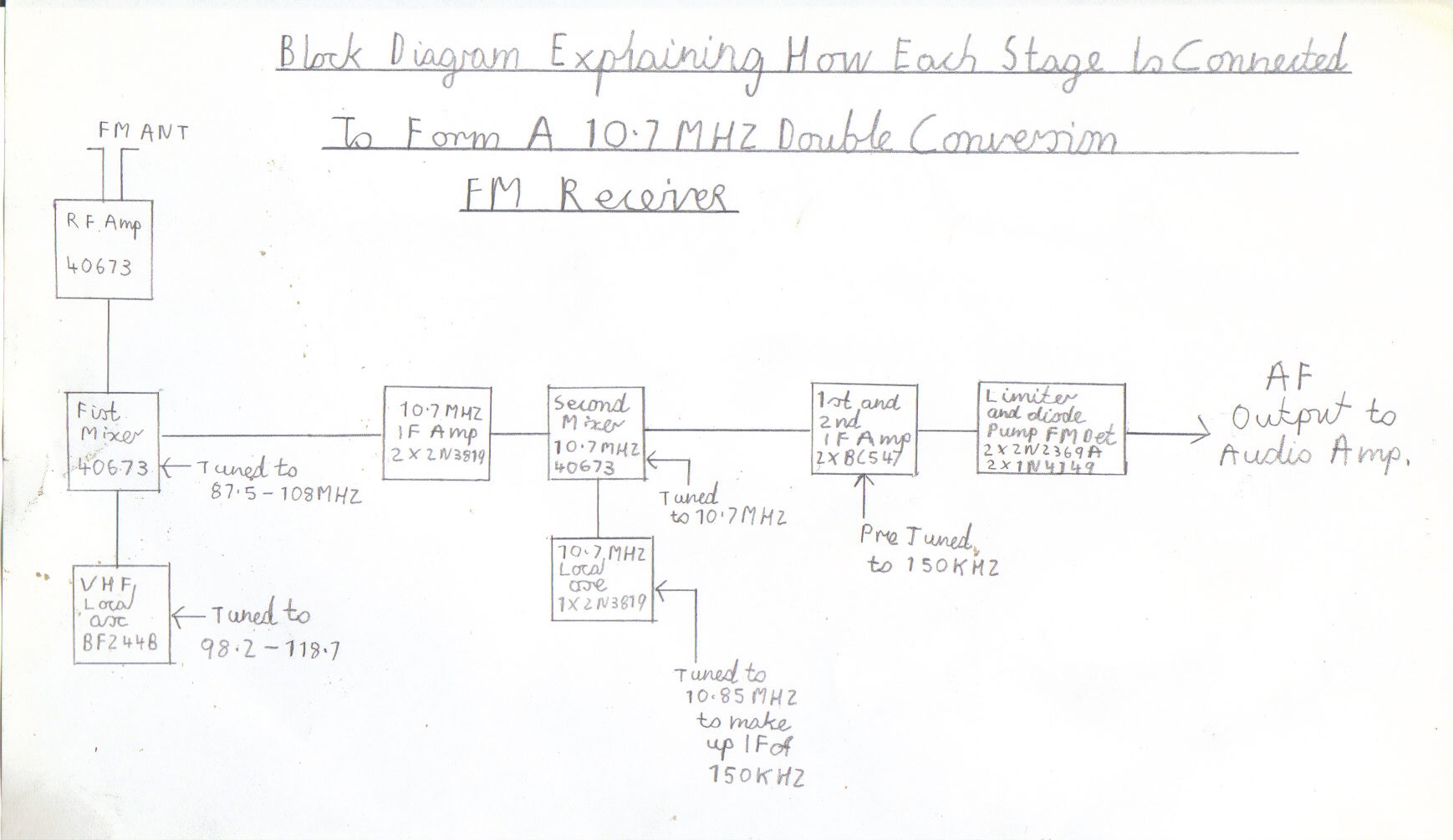
As you can see in the block diagram above this is a description of my design. Starting from right of the picture is the RF amplifier TR1/2 and like valve circuits it works in cascade mode consisting of 2, 2N3819 N-Channel FETs. Although it works quit well without it, Its purpose is to improve image response and help prevent radiation of the local oscillator. The mixer TR3 is a dual gate 40673 MOSFET and along with TR4 BF222B For the local oscillator this makes a very stable VHF receiver front end with no oscillator pulling, Compared to when you use a self oscillating mixer. The IF filter consists of a small resistance capacitor network to separate the VHF Megacycle Frequencies from the IF Kilocycle Frequencies, Which would otherwise result in severe IF breakthrough and instability. The other two stages TR5/6 consist of 2 BC547 Bipolar transistors for the Intermittent Frequency Amplifier and as this is a low IF of about 150Kc they are just resistance coupled amplifiers resulting in no coils to wind, Making the construction of this receiver more simple with less RF alignment. The final two stages TR7/8 Silicon 2N2369A transistors, Along with D1/2 1N4149 Silicon Diodes form the pulse counting FM Detector and unlike the 10.7MHZ Foster Seely Discriminator, There is again no alignment to worry about. The final stage IC 1 is the Audio Amplifier and as it requires no heat sink, It is simple to build using the popular LM386. Two separate 9 Volt Batteries are recommended for both the amplifier and tuner. The reason being, Is the current demand of the AF amplifier is quite high when used at high volume levels and can affect the tuning stability and also it is known to encourage HF instability, Particularly as the battery gets low. Starting with the 1st picture is my own working version of this receiver, Pictured in the living room with a short piece of wire for the aerial. Pictures 2 and 3 are the complete circuit diagrams of the FM Tuner and Amplifier. Pictures 4 to 8 are the wiring diagrams of each stage organised as a building block sequence, Starting from The Audio Amplifier to the final RF Stage to form this working VHF Radio. Please refer to the following guidelines and instructions below, Before proceeding with the construction of this receiver.
|
|
|
|
|
|
|
|
|
|
|
|
|
|
|
|
|
|
|
|
Please left click on selected pictures to enlarge image
Important things to bear in mind before constructing this receiver
Constructing a VHF receiver is as easy as constructing a medium wave design provided these certain rules are followed regarding the RF circuits and decoupling. Always try to keep leads as short and direct as possible that connect to the tuning capacitors and RF circuits. As you are dealing with a shortwave length of 100 MHZ, Every centimetre of lead counts as an inductance and long leads can lead to poor performance and instability. For the same reason although very tempting, Do not even think of adding bandswitching. The IF intermittent frequency circuits are not as critical as there are no coils to wind, But try to keep the wires as short as possible and not to crammed up. The decoupling on a VHF receiver is more important then the simple arrangement used with medium wave designs and if not done properly, It can result in severe HF and AF instability such as motor boating or squealing. For this reason 1000uf electrolytic capacitors and two separate 9V batteries have been chosen for the tuner and audio amplifier, When used as a portable receiver.
Special precautions concerning the batteries and transistors
Although there is no electric shock hazard with batteries there are few points you must bear in mind. When first testing this receiver it is advisable to use zinc carbon batteries or a regulated power supply incorporated with a current limiter for the following reason. The Ever Ready Alkaline Batteries recommended for this receiver deliver a very high current and under serious fault conditions such as short circuits, There is a risk of explosion or leakage. The FET Field effect transistors used in the RF circuits are very static sensitive and the following precautions must be carefully read. You need a whist strap and antistatic mat connected to earth through a 1 megaohm resistor. If you work mostly with valve equipment this precaution must be only on a temporarily basis as valves don't need this sort of precaution and can lead to a high risk of severe electric shock to earth. Avoid handling the transistors by there leads and try to use a plastic insulated tool to guide them into the circuit board. The use of a 25 watt Electric soldering iron is recommended along with some decent multicore solder designed for radio work. Also avoid applying to much heat to the joint when soldering the transistors by limiting the time to about 5 seconds maximum, Allowing just enough time to make a good clean joint. Also transistors are not as robust as valves, So make sure all the leads are connected in the correct orientation as shown on the circuit board or these devices could be permanently destroyed. The electrolytic capacitors marked with a + sign along with the batteries must always be connected with the correct polarity for the same reason.
Obtaining the components
It is very important that you have all the correct components to hand before even attempting to build this design. Certain components such as the field effect transistors and variable capacitors used in the RF circuits are no longer manufactured. There are however quite a few suppliers of old new stock components available but this is the same old phrase, First come first served, Hurry while stocks last I am afraid to say. It would also be advisable to purchase a couple of spares, Particularly the transistors for the very same reason. The following link Cricklewood Electronics CCTV and Electronic Components is very recommended and is where I managed to get almost all of the semiconductors and components for this design. At the time of writing this page the semiconductors still appear to be in stock so jump in there now to avoid disappointment
Constructing the receiver
The construction of this receiver has been made as simple as possible by dividing each stage into building blocks. As like valve circuits there is no metalwork required and no tasks such as heater wires to twist. It is advisable to build one stage at a time starting with the audio amplifier and working your way up to the RF Stage. As each stage is workable it is best dividing your time into separate evenings and avoid mistakes by not rushing into this popular phrase of I can have it up and running in a whole evening idea.
Building the audio amplifier
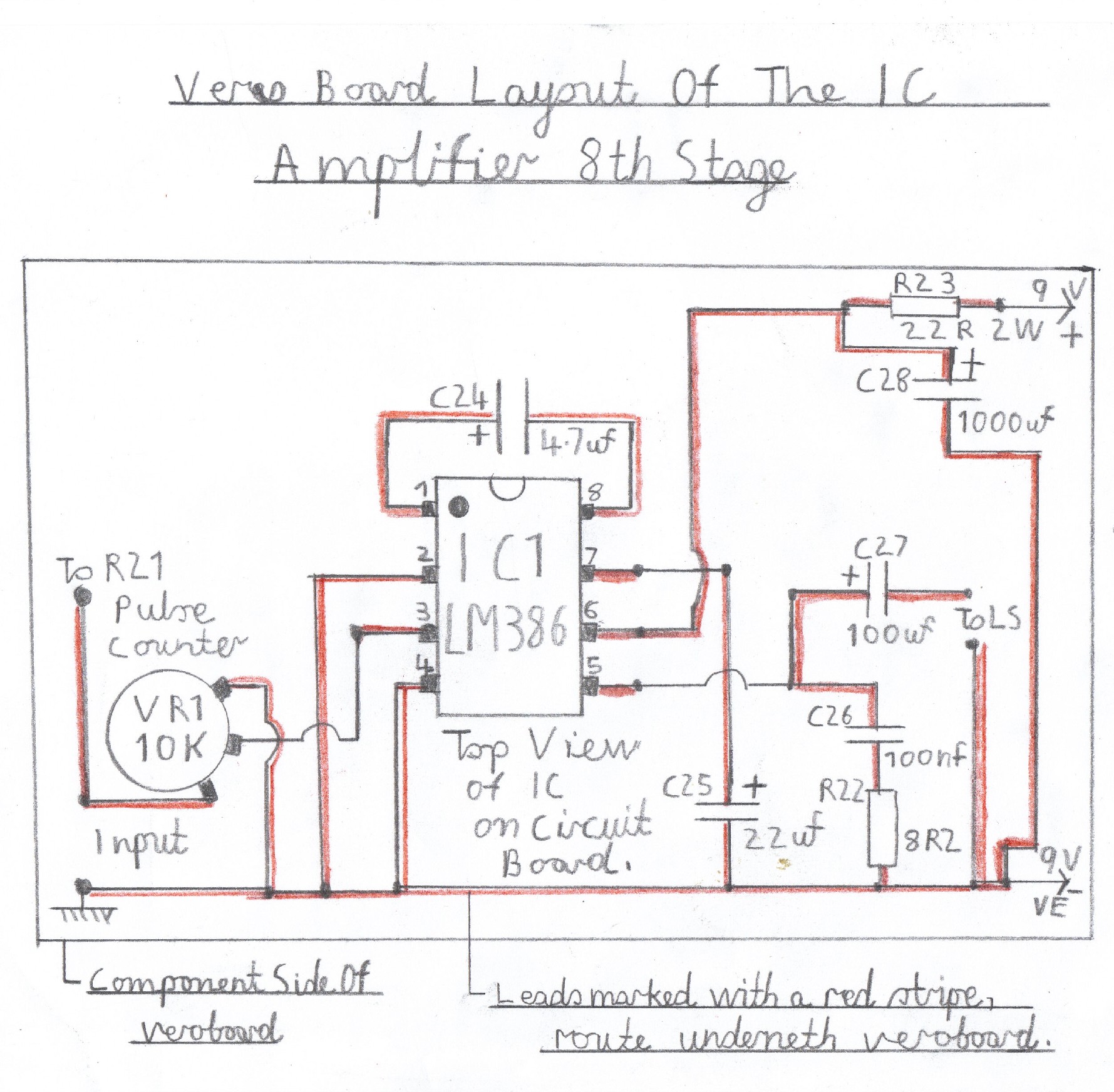
Please refer to picture 4 for construction of the audio amplifier. The leads marked with a red stripe are routed underneath the circuit board. The wires marked in black pencil are link wires and the same also applies to all the other building blocks that follow this circuit. The audio integrated circuit chip IC1 must be mounted into the 8 pin holder designed for this IC rather then soldering directly to the board making sure that the corner spot in the left corner corresponds with pin 1 as shown in the wiring diagram. The electrolytic capacitors C24 C25 and C27 must also be connected in the same polarity making sure the plus + sign corresponds the same way as shown on the board. Again this also applies to all the other circuits that follow. It is now time to test the audio stage by connecting any speaker of about 8 ohm to the output terminals. Connect a suitable 9 volt power supply in the correct polarity as shown in the diagram. If all is well, You should be able to hear a slight soft hiss. By advancing VR1 clockwise and touching the input you should hear a loud hum which means everything is working ok. NB Note regarding the use of another alternative amplifier. Due to my resent experience with the TDA7052 I would recommend sticking to the LM386 for this present design as I have found that the VHF local oscillator intercepts with certain ICs no matter how much you try to decouple stages. Valve amplifiers don't seem to have any problem and my new Double Conversion Pulse Counting FM Superhet Receiver With 10.7 MHZ First IF Stage also works great due to complete isolation of the VHF mixer and oscillator from the low IF stages.
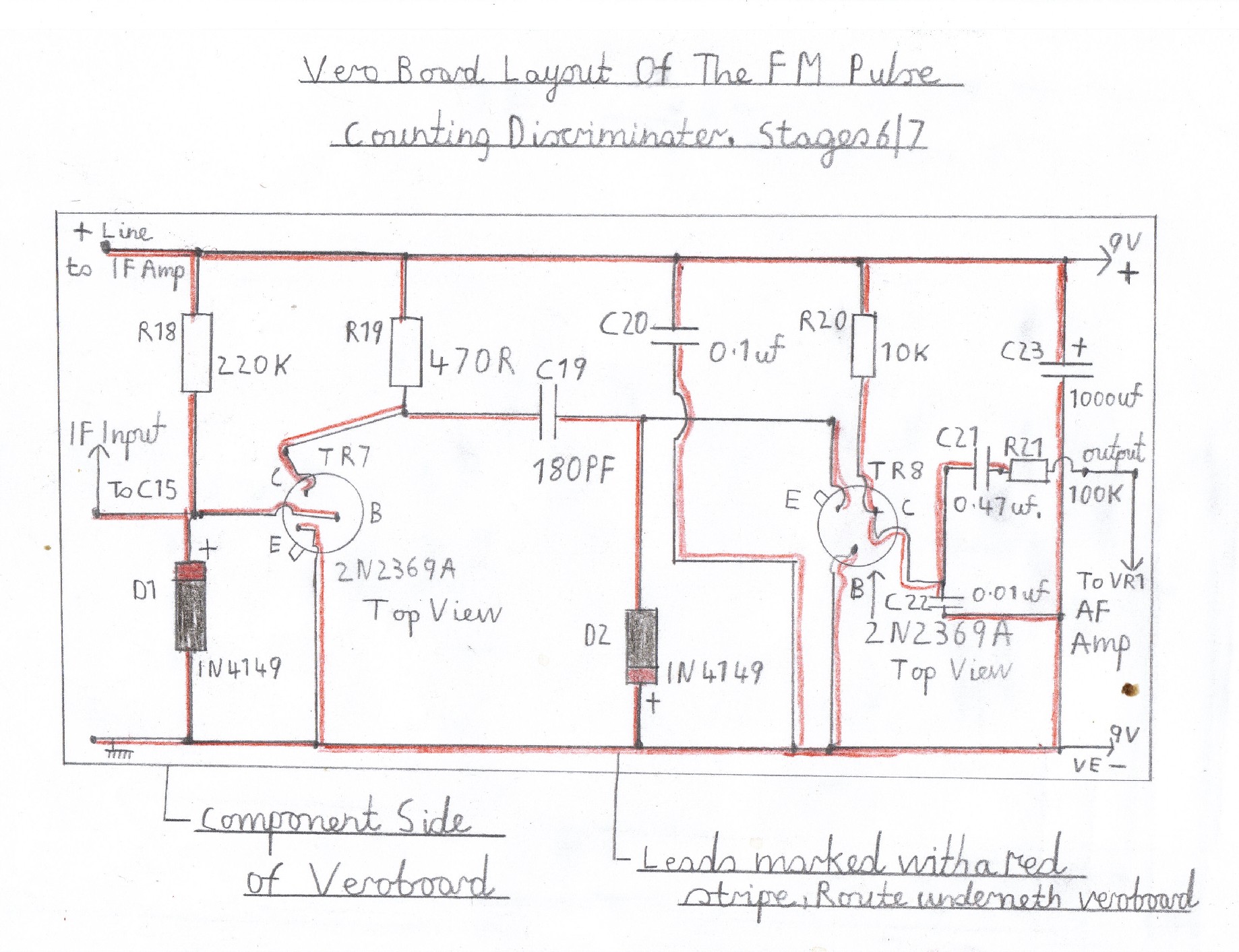
Building the Pulse counting discriminator
If all has gone well with building the audio stage then it is time to go ahead with building the pulse counter. Start by referring to picture 5 and follow the wiring diagram very carefully, leaving the transistors and diodes until last. The 2N2369A transistor leads have a metal fin which identifies the E, Emitter lead and this must correspond correctly as shown in the circuit diagram. The two 1N419 silicon diodes D1 and D2 have a red mark at the end and these must also correspond correctly as shown in the circuit diagram. It is now time to test the pulse counter. Start by connecting R21 to the input of the audio amplifier at VR1. Connect the 9 volt negative line from the pulse counter to the negative line of the audio amplifier and a second 9 volt battery to the 9 volt positive line on the pulse counter as shown. By touching the IF input at the junction of D1, R18 and TR7 base with a metal screwdriver you should hear some RF activity. Because this stage is acting as a untuned TRF receiver working on a long wave frequency of about 150 KHz, You will probably be able to hear BBC Radio 4 and a few other stations bunched up together. This means everything is again, Working well so far and it is now time to take a break before going ahead with the construction of the IF amplifier.
Building the IF Amplifier
The IF amplifier is also constructed in the same way as the pulse counter and the BC547 Bipolar transistors must also be connected in the same order as shown in the wiring diagram. They are a half moon shape and it is just a matter of making sure the flat surface corresponds correctly. The testing is also done in the same way as the pulse counter. Connect the IF output at C18 to the junction of R18, D1 and the base of TR7. Connect the negative earth line to the pulse counter earth and do the same with positive line as shown in the diagram. Reconnect the batteries and there should be even more signs of life. There should be quite a high pitched hiss and by touching C12 at the junction with C11 and R11 you should get the similar results you had when you were testing the pulse counter. If this is so You can, After a good nights rest go ahead with the VHF mixer and local Oscillator circuits, Which should be the real excitement. Notice concerning circuit correction. Due to one constructor having problems with this design I have checked and noticed a slight drawing error in the wiring diagram concerning picture 6. The R12 680K resistor should connect to the junction of R13/R14 and the base of TR5 BC547. Apologies for this mistake and I have now replaced picture 6 with a new diagram.
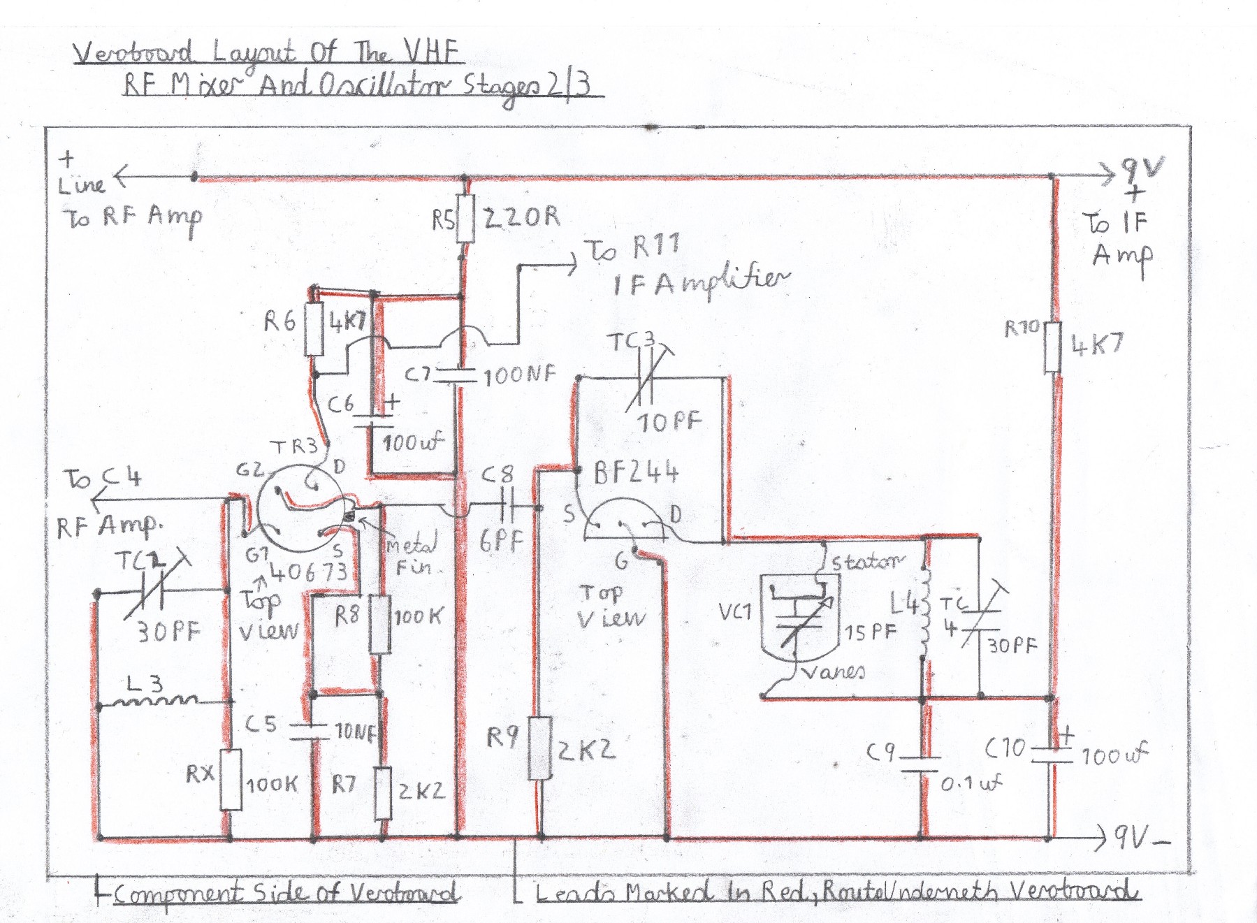
Building the VHF Mixer and Local Oscillator
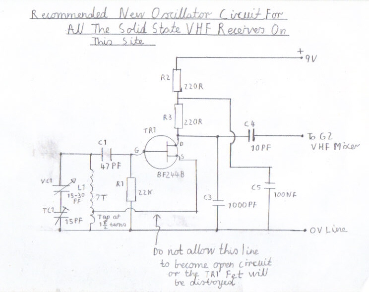
These are the two circuits that form the heart of the complete VHF receiver and is where great care in the construction must be taken. Picture 7 refers to the layout of both circuits and they must be wired with the components in the same order as shown in the diagram, With the wiring short and direct as possible. As I mentioned earlier on, Please take care when soldering The field effect transistors, Making sure you remember to ware your wrist strap at all times when handling them and not to apply to much heat when soldering. The 40673 dual gate MOSFET for the mixer has a metal fin between the source and drain leads and must be inserted into the circuit board as shown in the diagram. The same also applies to the BF244 oscillator transistor and is identified by inserting it with the flat surface corresponding as shown in the diagram. The RF Coils are self supporting and are wound with 16 SWG enamelled copper wire. Each Coil, L1 to L4 is wound with about 6 turns and has a diameter of about 10 millimetres. A winding tool, Such as a plastic tube is suitable for this and the coils must be soldered on to Vero pins, Mounted on the circuit board so they can be easily modified. TR 4 is arranged in a simple colpitts oscillator circuit along with VC1 for the main tuning. Because VC1 is at positive potential it is not possible to have duel gang tuning and for this reason, The mixer trimmer TC2 is broadly tuned to about the centre of the FM Band. Although This has a slight drawback I can receive all stations in the range of the 88 to 102 MHz part of the FM band very satisfactory. There is also another point concerning VC1 being at positive potential and also the problem of annoying hand capacity effects. If you deicide to enclose the receiver in a metal case, Earthed at negative potential this will cause a short circuit and drain the batteries. Hand capacity effects causing detuning of the receiver is also a problem with VHF and for both reasons it is recommended that you use some sort of spindle coupler and nylon rod for linking the tuning dial. NB A new circuit for the VHF oscillator has been tried just recently and has proven to be very successful. It uses a Hartley oscillator or better known as an electron coupled oscillator and has resulted in better stability and the tuning capacitor can now be grounded at earth potential eliminating hand capacity effects. A new circuit will soon appear as picture 18 and new constructers of this design should use this new circuit. Constructors using the present circuit are advised to modify the present circuit. Details will appear in this space soon.
Testing and aligning the receiver
Before connecting the mixer and oscillator, Please double check all wiring for any mistakes, Such as solder bridges, Wrongly placed components and of course the polarity of the transistors. Proceed by following these steps very carefully.
1. Connect the IF output from the junction of R6 at the drain of the mixer transistor TR3 to R11 of the IF Amplifier.
2. Connect the positive line of the mixer to the positive line of the IF Amplifier and also do the same with the negative earth return as well.
3. Do not connect the local oscillator at this moment or connect the L3 Aerial Coil.
4. Reconnect the batteries
5. You should now hear a background hiss, Similar to when you were testing the IF Amplifier.
6. By touching G1 of the mixer transistor, you should hear RF activity similar to that of the pulse counter and IF stages. If this is so, Disconnect the batteries and proceed to the next step.
7. Solder both coils L3/4 to there respective locations on the circuit board and connect the positive line of the local oscillator, To the positive busbar on on the mixer at R5.
8. Connect a temporary short piece of wire of say a metre or better still, A decent outdoor FM antenna, Centre tapped at L3 with the outer braid connected to earth.
9. Reconnect the Batteries and this should be the great moment of truth.
10. Try rocking the VC1 Tuning capacitor around midway and you may be able to tune a couple of stations, If all has gone well.
11. If reception is a bit weak and distorted, Try moving the Aerial wire in different directions until signal strength improves.
12. Now adjust TC2 for maximum signal strength.
13. Try to find BBC Radio 2, Which is at the lower end of the FM band towards 88MHZ.
14. TC4 is the local oscillator trimmer and is used to bring the tuning correctly inline with VC1. However this is done with trial and error which I will describe how to proceed.
15. For example, A normal FM receiver starts with its frequency coverage in the following order 0f 88 to 108 MHZ. Radio 2 broadcasts on about 89.3 to 90.2 MHZ.
16. If you find you are receiving Radio 2 with the VC1 Tuning capacitor vanes half way open, This needs correcting. Start by slowly opening the vanes of the TC4 Oscillator trimmer. If you now start closing the vanes of VC1, You should be able to retune to radio 2. You need to do this several times until you can receive Radio 2, With the vanes of VC1 just open around 3 millimetres from its extreme maximum capacitance.
17. If all the above steps have gone ok, It is now time to start with the aerial tuning alignment.
18. Retune the radio to a station on the higher frequency part of the band, For example Radio 4. Readjust the mixer trimmer TC2 for maximum signal strength.
19. Repeat step 18 and try retuning to some of the local Radio stations around 95.9 MHZ. Readjust TC1 again for maximum signal strength.
20. Keep repeating this step several times until you can reasonably receive strong stations on all parts of the band, With minimum background hiss and no distortion.
21. TC3 is the oscillator regeneration feedback control. You may also have to adjust this if you find that the oscillator comes to a halt, When tuning from one end of the band to the other. Again this is with trial and error.
22. If you have completed all these steps carefully, You should now have a working FM Superhet receiver that is something for you to be proud about. However. It is not advisable to continually use it in its current state for the following reason. I have noticed the local oscillator on this receiver does radiate slight RF interference when used in the proximity of other VHF receivers around my home, particularly when tuned to the same stations. To eliminate this, It is advisable to build the mixer and oscillator stages into a shielded metal box, With the addition of the final RF Stage featured below should also help.
Building The RF Amplifier
The RF amplifier is basically built in the same manner as the mixer. You must first refer to picture 8, Making sure that you keep all the RF leads to the trimmer and VHF coils, As short as possible. The 2N3819 FET transistors must also be treated with care, In the same way as when you constructed the mixer and oscillator circuits. The RF coils are also constructed with the same number of turns and physical dimensions as the mixer and oscillator circuits. It is now time to test and align the RF Stage. First connect the positive line of the RF stage to the positive rail, At the junction of R5 and R10 on the mixer. Now connect the RF output from C4, To the junction of L1, TC2 and Gate 1 of the TR3 mixer transistor. Next connect the negative earth return to the negative line on the mixer and reconnect the aerial to the L1 RF coil, Tapped at about two turns from the earthy end. Reconnect the receiver and if all is well you should be able to still tune in some of the same stations as before. In the same way as you aligned the mixer, Adjust TC1 for maximum signal strength, Repeating the same procedure several times at both ends of the band. You should now have a working and complete FM radio of all your own work
Finally
I hope all you readers enjoy this page regarding my construction of this exciting project and will in the later life of this page, Take the courage to have a go yourselves. Although this is designed as a battery portable receiver it can be put in to use as a Mono HI FI tuner and the LM386 IC Amplifier omitted, Replacing it with any mains operated power amplifier, Transistor or valve. There is now a new design of this receiver available by clicking the following link Double Conversion Pulse Counting FM Superhet Receiver With 10.7 MHZ First IF Stage and also some additional information below on how to convert this design. This tuner is now also stereo compatible. Picture 11 is a phase correction circuit that must be wired ahead of the pulse counting detector to follow the multiplex input on the decoder. Stereo reception requires a good signal of about 60db minimum to work properly, so a decent high as possible outdoor antenna is essential. Please refer to the following link FM Stereo Decoder Circuit . Other stereo decoders may work, but may need additional input preamplification to work properly.
Components List
Please refer to the following link Components List For Transistor FM Receiver
Converting This Design Into A 10.7 MHZ Double Conversion FM Receiver
Although this present single conversion FM superhet receiver gives excellent performance, I have decided to add some additional pictures and information on how to convert this design into my latest Double Conversion Pulse Counting FM Superhet Receiver With 10.7 MHZ First IF Stage . Please read the following steps before proceeding.
1. Newcomers to VHF or superhet receiver construction are best sticking to this present single conversion design, until they have gained sufficient experience with how to align RF circuits and knowledge of how superhet receivers work. It is also essential to have possession of an RF signal generator, as there are more RF stages to align and they all must be really spot on for the design of a double conversion receiver to perform really well.
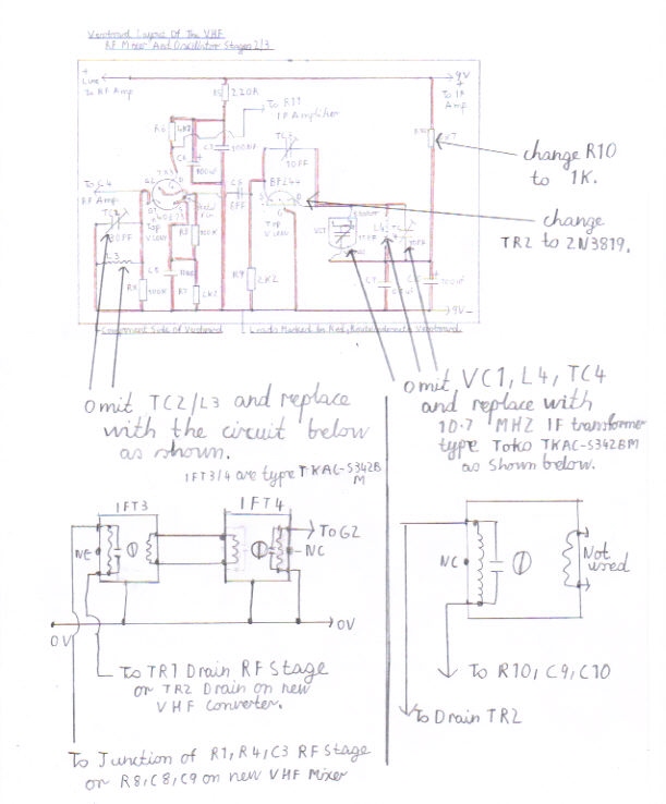
2. Please refer to picture 12 which explains on how to tackle the conversion of the present VHF mixer to which will become the second 10.7 MHZ mixer and local oscillator.
3. Click on the following link Double Conversion Pulse Counting FM Superhet Receiver With 10.7 MHZ First IF Stage and refer to step 8 which tells you how to align the 10.7 MHZ mixer and local oscillator
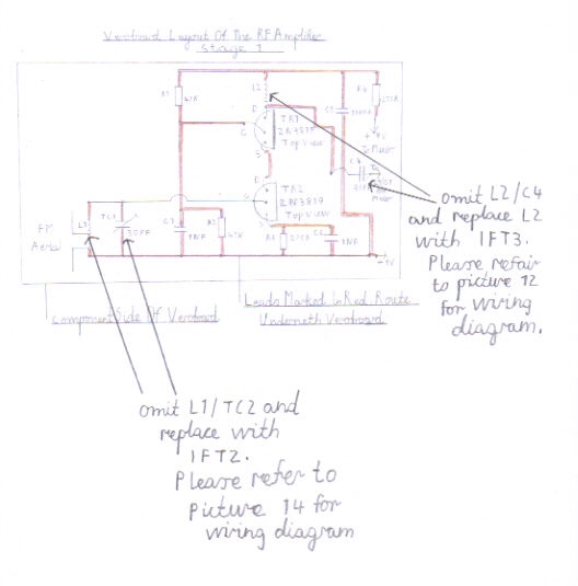
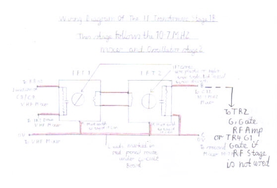
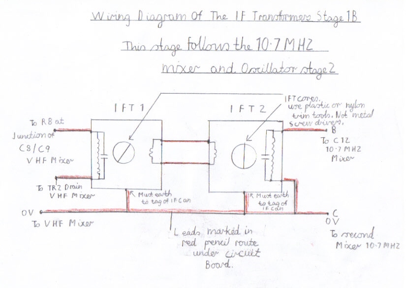
4. If the above step regarding the alignment of the new 10.7 MHZ mixer has gone ok, You need to refer to picture 13 which tells you how to modify the the present VHF RF amplifier to a new 10.7 MHZ IF amplifier and believe me this will give even more improved performance. You also need to refer to picture 14 which gives additional information on the wiring of IFT 1 and IFT 2 that follow the input of the 10.7 MHZ IF amplifier. Although picture 14 is not a very clear diagram due to it being scanned, you can get a better picture by clicking the following link wiringdiagramofiftransformersone.jpg . Please repeat the above step for aligning this stage. Also please bear in mind, that you can skip this step if you have not added the IF amplifier and proceed to step 5.
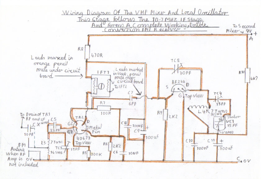
5. Please refer to picture 15 for the wiring diagram of the new VHF mixer that will now follow the new 10.7 MHZ IF stage.
7. Please click on the following link Double Conversion Pulse Counting FM Superhet Receiver With 10.7 MHZ First IF Stage and refer to step 10 for aligning and setting up the new VHF mixer.
8. Please refer to pictures 16 and 17 which shows you my single conversion FM receiver, after the double conversion to give you all an example of which stages have changed. Also please refer to picture 18 which is the block diagram of this 10.7 MHZ FM Receiver configuration to give you an idea of how the stages are connected up.
Links To My Other FM Receiver And Hi Fi Projects
Double Conversion Pulse Counting FM Superhet Receiver With 10.7 MHZ First IF Stage
Single Conversion 6 Transistor 10.7 MHZ Pulse Counting Receiver, Designed For Stereo FM Reception
6 Valve VHF/FM Pulse Counting FM Tuner Using Safe 25Volt DC HT Line
Valve Version Of The 10.7 MHZ Double Conversion VHF/FM Pulse Counting Tuner
Solid State AM/FM Pulse Counting Receiver
Site Map Of All My Webpages And Favourite Valve Radio Related Links


